Simplified Inverter-Based Generation Model for Protection and Short-Term Stability Studies in Electromagnetic Transient Resolution
Modelo simplificado de generador basado en inversores para estudios de protecciones y estabilidad de corto plazo en resolución de transitorios electromagnéticos
 PDF
PDF
Received: March 17, 2022
Accepted: September 19, 2022
Available: November 9, 2022
D. Sánchez-Muñoz, E. Pérez-González, J. F. Piñeros, L. Agudelo-Zapata, “Simplified Inverter-Based Generation Model for Protection and Short-Term Stability Studies in Electromagnetic Transient Resolution,” TecnoLógicas, vol. 25, nro. 55, e2347, 2022. https://doi.org/10.22430/22565337.2347
Highlights
Abstract
The new dynamics of inverter-based generation (IBG) and the lack of accurate models jeopardize the safety of power systems. Additionally, most of the detailed models for electromagnetic transients (EMT) from manufacturers are black boxes. For this reason, the objective of this work was to propose a generic IBG model in EMT resolution suitable for short-circuit, protections, and short-term voltage stability studies. For this purpose, the model considered different functionalities, such as synchronization in case of unbalanced voltage sags, flexible negative sequence current injection, peak current limitation, dynamic reactive power control, and fault ride-through (FRT). This model allowed grid operators to meet the challenge of performing accurate simulations with high integration of renewable resources in their energy matrix. The model was also based on a voltage-controlled current source in the ATP/EMTP software. The short-circuit response was evaluated in a simulation scenario for different fault events presenting a reliable behavior due to the consideration of technical and regulatory requirements and constraints of IBGs. Finally, the proposed model has a fast initialization and is suitable for simulations with large time steps, making it valuable for EMT simulations in large grids.
Keywords: Grid-side converter, short-circuit current, controlled current source, inverter-based distributed generation, inverter EMT modeling.
Resumen
Las nuevas dinámicas de la generación basada en inversores (IBG) y la falta de modelos precisos ponen en peligro la seguridad de los sistemas de potencia. Adicionalmente, la mayoría de los modelos detallados para transitorios electromagnéticos (EMT) de los fabricantes son cajas negras. Por esta razón, el objetivo de este trabajo fue proponer un modelo de IBG genérico en resolución EMT apropiado para estudios de cortocircuito, protecciones y estabilidad de tensión de corto plazo. Para ello, el modelo consideró diferentes funcionalidades, como sincronización ante huecos de tensión desbalanceados, inyección flexible de corriente de secuencia negativa, limitación de corriente pico, control dinámico de potencia reactiva y soportabilidad ante fallas (FRT). Este modelo permitió a los operadores de red enfrentar el reto de realizar simulaciones precisas con gran integración de recursos renovables en su matriz energética. El modelo, además, se basó en una fuente de corriente controlada por tensión en el software ATP/EMTP. La respuesta de cortocircuito se evaluó en un escenario de simulación para diferentes eventos de falla presentando un comportamiento confiable debido a que se consideran los requerimientos y limitantes técnicas y regulatorias de los IBG. Finalmente, el modelo propuesto tiene una rápida inicialización y es apropiado para simulaciones con grandes pasos de tiempo, haciendo que sea valioso para simulaciones EMT en grandes redes.
Palabras clave: Convertidor del lado de la red, corriente de cortocircuito, fuente de corriente controlada, generación distribuida basada en inversores, Modelado EMT de inversores.
ABBREVIATIONS
| EMT | Electromagnetic Transient |
| IBG | Inverter Based Generation |
| DSOGI | Double Second Order Generalized Integrator |
| IGBT | Insulated Gate Bipolar Transistor |
| FLL | Frequency Locked Loop |
| FRT | Fault Ride Through |
| HVRT | High Voltage Ride Through |
| LVRT | Low Voltage Ride Though |
| PCC | Point Common Coupling |
| PLL | Phased Locked Loop |
| TSO | Transmission System Operator |
| WTG | Wind Turbine Generator |
1. INTRODUCTION
Nowadays, electric power systems are in a rapid change of the global energy matrix pushed mainly by decarbonization goals and cost reduction of new technologies [
Several studies have been carried out dealing with the new dynamics of IBG sources in power systems. For example, a comprehensive review of the IBG technology dealing with the inertia and frequency control issues is presented in [
In this sense, IBGs are introducing new dynamics to the power system that may be studied in detail to analyze the power system’s impact, particularly to the already installed control and protection equipment [
Different efforts have been made to develop models that may reproduce the new dynamics of the IBGs. In [
Further, in [
Understanding the importance of IBGs accurate modeling for transient studies and the difficulty of obtaining the manufacturer detailed EMT models, studies such as [
Authors of [
Additionally, real-time simulators and hardware in the loop are increasingly used to face high IBG penetration issues.
Moreover, [
This paper discusses integrating a generic EMT IBG power plant model as a controlled current source as an enhanced version of the article presented in Symposium X SICEL 2021. This model is implemented in EMTP/ATP software, including all the necessary functionalities to evaluate short circuit studies and protection schemes. The main functionalities are a flexible positive-negative current control injection, current limitation, dynamic reactive power support, and programmable fault ride-through. It has advantages such as less computational load, fast initialization, and the capability to be executed with time step sizes up to 200 μs with average errors of less than five percent. The implemented inverter model considers control and protection characteristics that allow calculating the short-circuit current and understanding the dynamic behavior of IBG to different types of internal and external faults, according to the design and control strategy implemented in the inverter. This paper’s structure is presented below; chapter 2 presents the methodology for the developed model using a voltage-controlled current source, describing the considered functionalities, and evaluating its behavior for unbalanced short-circuit events; chapter 3 presents the discussion of the proposed model. Finally, chapter 4 presents the conclusions.
2. METHODOLOGICAL ASPECTS
The proposed model for EMT simulation for fault studies is based on a controlled current source representation [
2.1 Grid side inverter control
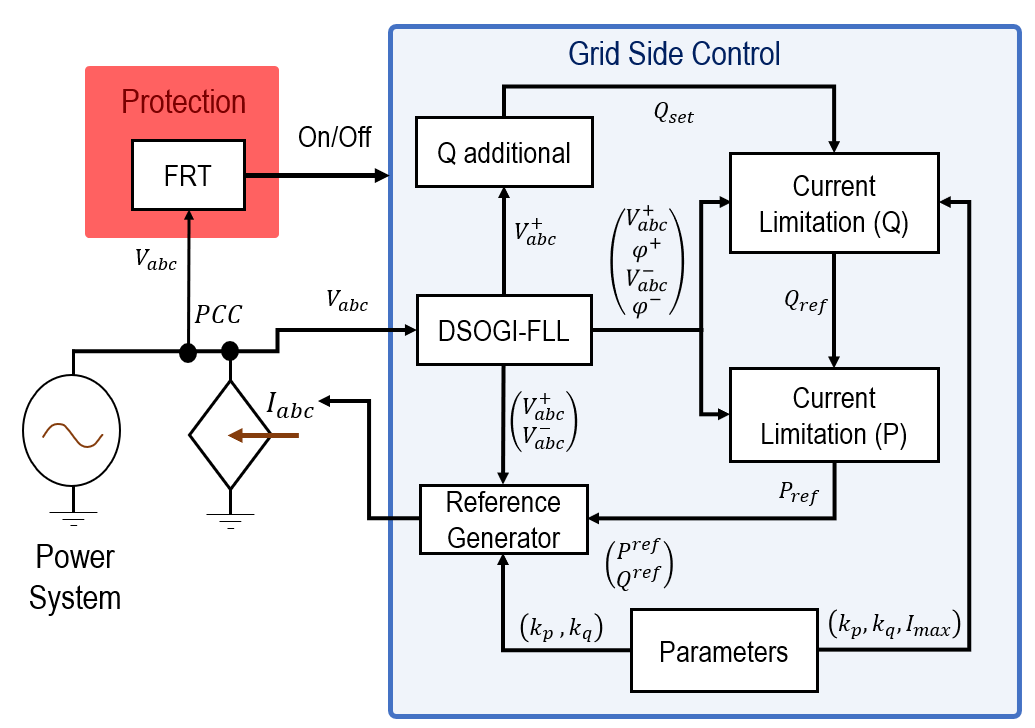
The developed model has five blocks describing the grid side inverter’s main components in IBG power plants and one additional block to improve the simulation initialization.
- Three-phase grid synchronization under unbalanced voltage conditions
- Flexible control strategy for current injection.
- Peak current limitation of current injection.
- Dynamic reactive power control.
- Fault Ride Through (FRT) characteristic.
- Controlled current initialization.
Figure 2 presents the structure of the Grid Side Control implemented for the controlled current source model.
2.1.1 Unbalanced grid synchronization
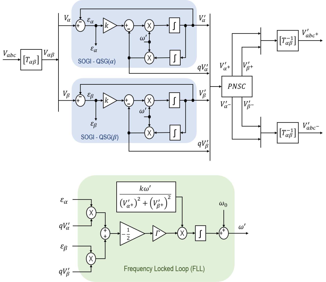
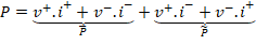
Since most short-circuit events in three-phase grids are unbalanced, and this imbalance is noticeable enough to be neglected, correct grid synchronization for unbalanced voltage dips is required. In this case, a Double Second Order Generalized Integrator – Frequency Locked Loop (DSOGI – FLL) is implemented as presented in [
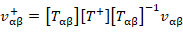

Where, [Tαβ] is the αβ transformation matrix, [T+] and [T -] are the well-known Fortescue transformation matrix for symmetrical components. Simplifying (1) and (2), (3) and (4) are obtained, where q operator represents 90-degree lagging-phase shift in the time domain.


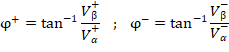
Finally, the Positive – Negative Sequence Calculator (PNSC) block calculates the positive and negative sequence voltage in αβ reference frame, as shown in (5). Additionally, the positive-negative sequence voltage angle (φ+, φ-) can be calculated using (6). Figure 3 shows the structure of DSOGI – FLL.

2.1.2 Injection current control
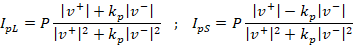
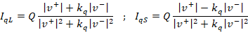
The IBG power plants use a control block in charge of generating the current references to meet an active and reactive power setpoint given a PCC voltage condition. Moreover, for three-phase inverters, the zero sequence components are ignored, then the instantaneous active and reactive power in the PCC could be calculated using (7) and (8).
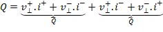
Where the indices “+” and “−” represent the positive-negative sequence. The active-reactive power equations are grouped into two terms respectively, P ̅ and Q ̅ are the active and reactive powers resulting from the interaction between the voltages and currents of the same sequence. On the other hand, P ̃ and Q ̃ are the active and reactive powers resulting from the interaction of the voltages and currents of different sequences. Additionally, the “⊥” operator denotes a 90-degree lead-phase shifting vector rotation.
Due to IBG’s current injection depends on the control scheme, current references can be defined in many ways according to specific objectives, which impact the magnitude and phase of the short-circuit current injected per phase [
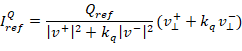
Adjusting kp and kq, could have infinite control modes where several authors focus in three particular control strategies [
-
Constant active power control: There is cancellation of the active power oscillations, and there is negative sequence current participation. (kp = 1 y kq = −1).
-
Balanced current control: The injected current only has a positive sequence component and oscillations in the active and reactive power. (kp = 0 y kq = 0).
- Constant reactive power control: There is negative sequence current participation and the cancellation of the reactive power oscillations (kp = 1 y kq = −1).
Authors in [
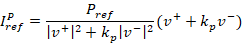
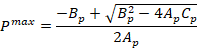
2.1.3 Injection current limitation
As presented in the previous section, current references are built using active-reactive power references and the PCC voltage condition. This means that under severe faults (large low voltage drops, if the power references are not modified, the current reference could be greater than the maximum current bearable by Insulated Gate Bipolar Transistor (IGBT). For this model, it is implemented a current limitation strategy based on the ellipsoid theory described in [

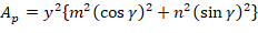
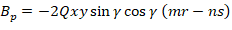
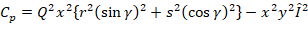
The active power limit is found by setting a reactive power reference and vice versa. Therefore, in (15) – (18) determine the maximum active power allowed considering the reactive power reference without exceeding the maximum IGBT’s peak current supportability.
Equations (19) – (22) determine the maximum reactive power allowed considering the active power reference without exceeding the maximum IGBT’s peak current supportability.
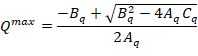
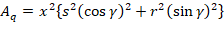
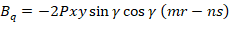

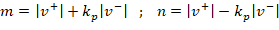
Where m, n, r, s, x and y are scalar values given by (23) – (25):
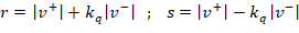

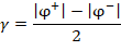
Equation (26) define parameter γ that allows computing the maximum active and reactive power for phases B and C.
Therefore, the active-reactive power limit (Plim, Qlim) is constrained by the lower active-reactive maximum power between all phases as shown in (27) and (28).
2.1.4 Dynamic reactive power control
Reactive power support control in IBG power plants is necessary to achieve better short-term voltage stability [
Figure 4 shows the general structure of the dynamic power control. This strategy calculates an additional reactive power quantity to be added to the pre-fault reactive power.
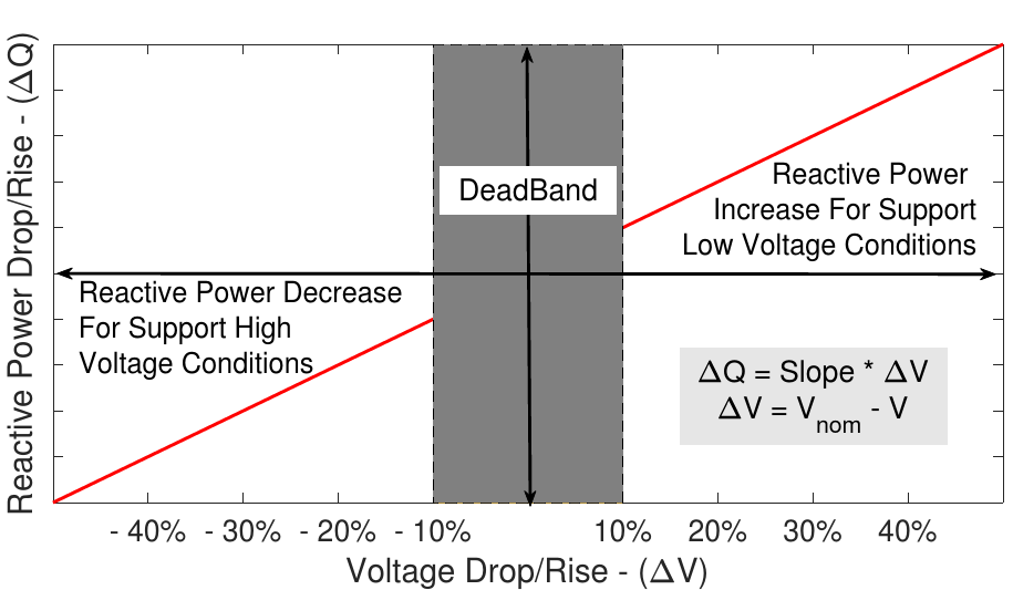
This new reactive power setpoint is an input for the active power curtailment block and the current reference generator.
2.1.5 Fault Ride Through (FRT)
Most TSO grid codes require that IBG power plants keep their operation during voltage disturbances to increase the security of the operation over short-circuit events [
2.1.6 Controlled current source initialization
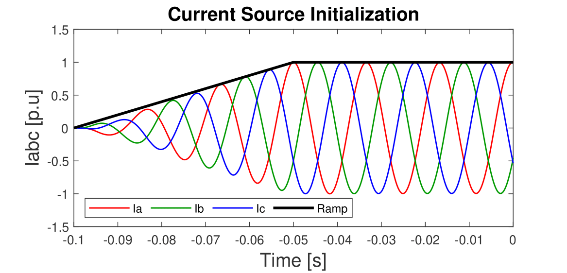
For EMT short circuit studies is very important to have fast initialization to improve computational load. Traditionally, the power-flow initial condition is adjusted to set appropriate values; however, it could be cumbersome for large studies where load and generation condition is varied. This work proposes soft transient grid synchronization initialization based in two stages of the current injection setting:
- Second-Order Band Pass filter with cut frequency ωn = 377 rad and quality factor Q = 0.5 in the first 50 ms of simulation. This stage reduces the current components with different frequencies from the nominal.
- Ramp start from 0 p.u to 1 p.u. in the first 50 ms of simulation. This stage generates linear growth in order to avoid PCC voltage distortion. Figure 5 shows IBG current during the initialization stage, going from zero to its nominal value in 50 ms. Also, at this point, the reader may notice how the controlled current source model approach takes approximately 50 ms to initialize, which improves the initialization efficiently.
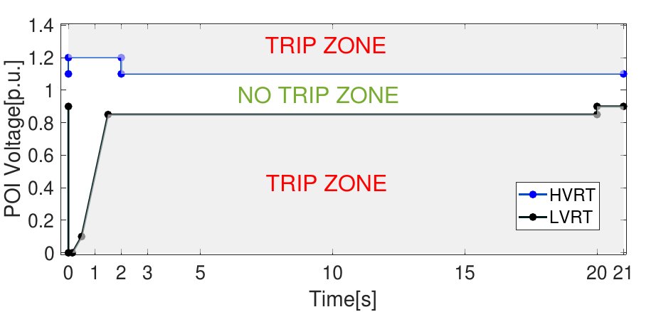
Figure 6 shows IBG current during the initialization stage, going from zero to its nominal value in 50 ms. Also, at this point, the reader may notice how the controlled current source model approach takes approximately 50 ms to initialize, which improves the initialization efficiently.
2.2 IBG model validation
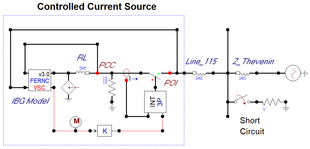
This section analyzes the IBG model for single-phase faults and evaluates its performance on time step simulation. Figure 7 shows the study case of the grid implemented for testing the performance of the IBG controlled current source model. The circuit includes a Thevenin’s Voltage Source (Grid), a positive-zero sequence impedance to connect the IBG Power Plant to the grid, a resistive branch to the ground for short circuit events, and finally, the IBG model without a transformer. Additionally, Table 1 shows the parameters used for the grid configuration. In all cases, a single-phase fault of 0.1 Ω is simulated at 50 ms and cleared at 150 ms except for the case of FRT.
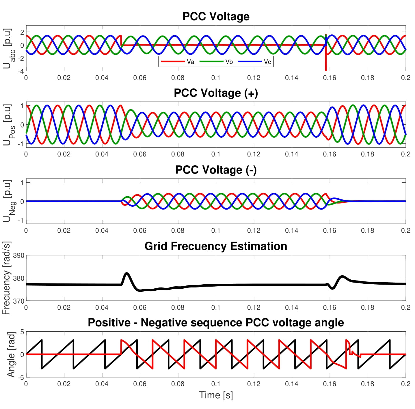
2.2.1 Grid synchronization
The frequency estimation by the DSOGI – FLL is verified and the decomposition of the PCC voltage in positive and negative sequence with their respective angles. Figure 8 shows the PCC voltage and its positive-negative sequence decomposition, the estimated frequency, and the positive-negative sequence voltage angles. A DSOGI – FLL relevant aspect is the smooth response to sudden voltage changes produced by switch events like the fault inception or the fault clearance.
2.2.2 Current control strategies
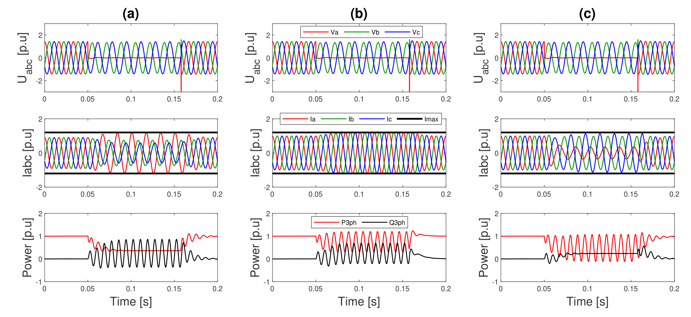
The control strategies and current limitation play the major dynamic variation on short circuit conditions. Figure 9 is presented the results for three current control strategies, with a slope Qk= 1 and a current limitation of Imax = 1.2 Inom. For constant active power control, the current of the fault phase increases its value and is limited by the current limitation module. On balanced current control, the current is enhanced balanced in the three phases and once is limited by the current module. Furthermore, in the constant reactive control, the current of the fault phase is reduced its value, and the other two are enhanced. These dynamics generate different challenges for detection using traditional protection schemes.
Since several protection schemes use negative sequence, Figure 10 shows the sensitivity of positive and negative current amplitude when the control variables kp and kq are swept between [−1, 1]. The peak current limitation is settled in Imax = 1.2 Inom.
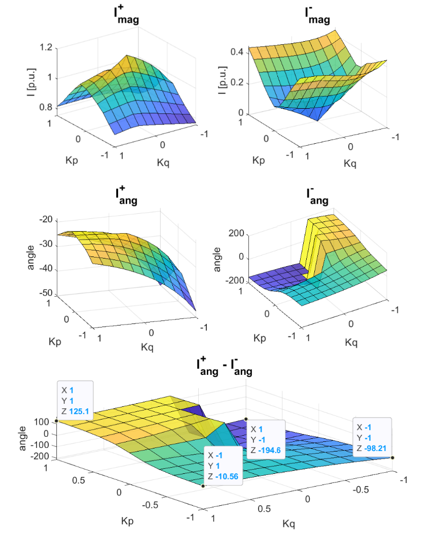
From kp– kq swept analysis, we can notice that the maximum negative sequence quantity appears in extreme parameter values, and the significant positive sequence quantity appears with the closest to zero parameter values. The reader can also notice how the positive-negative sequence current angle is more sensitive to the kq factor. Additionally, the phase angle difference (I+ang-I-ang) for constant active power control is the shortest −10.56º (I+ang approximately in phase with I-ang) and for constant reactive power control is the largest −194.5º (I+ang approximately opposite to I-ang). For this reason, phase A current magnitude is the largest in the first case and the shortest in the second case. This behavior is quite different from a synchronous machine with the same rated power. Figure 11 is shown the dynamic of the current and power when a single-phase fault occurs.
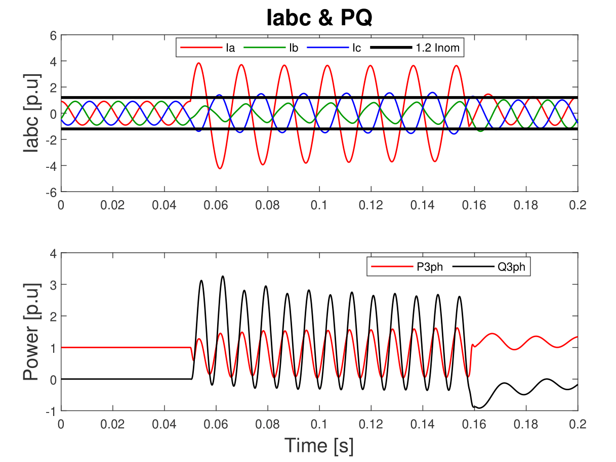
It can be seen how there are oscillations in the active-reactive power delivered by the synchronous machine under fault conditions. However, the reactive power magnitude oscillations are more than twice the active power magnitude oscillations, finding that the reactive power oscillations are predominant for the synchronous machine under single phase to ground short-circuit. Additionally, the current of the failed phase is greater than the healthy phases presenting a similar behavior similar to the constant active power control current strategy without current limitation shown in Figure 8 (Of course, with an IBG lower peak current).
2.2.3 Dynamic reactive power support
For this section, an impedance fault sweep is performed to verify the active-reactive power injected related to the PCC voltage deviations considering the three control modes and the inverter current limitation.
The dynamic reactive power control is configured with a slope Qk = 1. Figure 12 shows the dynamic reactive power injection with the active-reactive power curtailment due to limiting peak current for single-phase to ground failures (Ag) and isolated two-phase failures (AB).
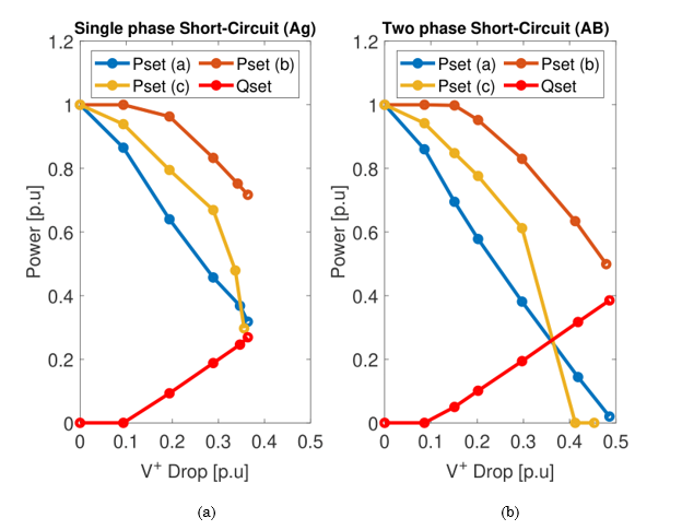
Considering that the amount of reactive power to compensate is equal for the three control strategies, it is clear how the Balanced Current Control strategy offers better performance regarding power injection. Furthermore, the behavior of the reactive power support does not depend on the type of short-circuit events attending to the slope Qk desired and the configured dead-band.
2.2.4 Fault ride through
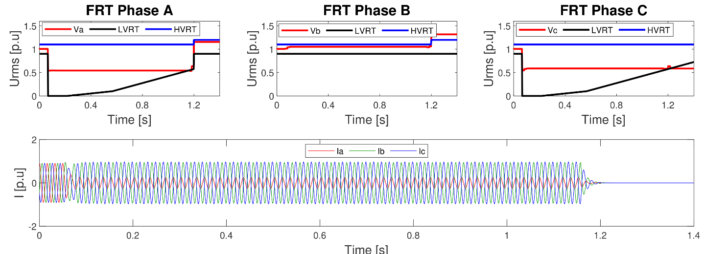
The PCC voltage per phase is compared with the HVRT and LVRT curves to decide if the plant should be kept connected or may be disconnected from the network. Figure 13 shows the FRT behavior, presenting IBG disconnection close to 1.2 seconds, presenting that IBG plant remained under abnormal voltage conditions for more than 1.1 seconds.
2.2.5 Time step performance
This section presents the average error of the IBG injected current for different simulation step sizes. The theoretical waveform will result from the simulation with a step size of 1μs. Table 2 shows the obtained results from this analysis. In contrast, [
| IBG current error (%) | |||
| Step Size (µs) | Phase A | Phase B | Phase C |
| 10 | 0.207 | 0.207 | 0.209 |
| 50 | 1.128 | 1.130 | 1.145 |
| 100 | 2.294 | 2.300 | 2.329 |
| 200 | 4.714 | 4.720 | 4.750 |
| 500 | 11.727 | 11.738 | 11.846 |
| 1000 | 25.294 | 25.450 | 25.508 |
| 2000 | 55.843 | 55.856 | 55.906 |
3. RESULTS AND DISCUSSION
As mentioned in this paper introduction, authors in [
With this aim, an IBG model in EMT resolution with a low computational cost suitable for simulations with big-time steps is proposed in this work. In [
-
Discrete switch model: Essentially, it requires modeling each of the discrete switches (IGBT, Diode, Thyristor, etc.). As an advantage, the results are the most accurate, but it requires small simulation steps (less than 10 µs) and requires inner PI control and a PWM module for switch activation-deactivation. As a consequence, it is the interface type that generates the bigger computational load.
- Average switch model: Collapse in each time step the discrete switches in a Thevenin equivalent using a forward-backward process. It is more efficient than the Discrete Switch Model. Requires inner PI control; it reproduces the Discrete Switch Model overall response including harmonics correctly but without the ripple.
-
Simple source model: Takes output current reference signals and injects these signals into the grid as current injections. It is exceptionally efficient as it does not need IGBTs or inner PI control. Also, it does not generate harmonics due to IGBT operation. A disadvantage is that it can be quite unstable in a non-iterative solution and are not appropriate for detailed studies.
In this paper, a "Simple Source Model" approach is implemented as is the most economic interface in terms of computational cost. This model is accurate enough for short circuit and stability simulations with objective protection studies and control stability of the inverter in weak grids during faults processes (fault and fault clearing).
4. CONCLUSIONS
This paper presented a generic simplified EMT model for IBG power plants focused on short-circuit and short-term voltage stability to perform studies, including protection coordination. The presented voltage-controlled current source focus is practical and efficient that allows simulations with initialization times close to 50 ms and simulation step sizes of up to 200 us with errors of less than 5%. It integrates all the necessary functions to perform accurate simulations about transient and steady-state IBG behavior in EMT simulations. The presented model offers grid synchronization under all types of unbalanced voltage dips, making all kinds of perturbation feasible. Further, this model integrates flexible positive-negative sequence current injection, which makes possible the study of the impacts of suppressing negative sequence quantities. This model offers peak current limitation, which is IBG limitation in terms of reactive short-circuit current capacity and affects protection schemes.
The model's features allow us to understand and evaluate the behavior of IBG generation during faults and give recommendations to improve the performance of protection systems in grids with high IBG penetration. The presented model also has dynamical reactive power support under-voltage conditions. This feature is necessary to reproduce the IBG response under-voltage deviations. Finally, this model includes programmable FRT capabilities, which accurately indicate how IBG will ride through abnormal voltage conditions for analyzing voltage stability and protection coordination. This model obtains reliable results due to it considers technical and mandatory requirements of inverter-based generation.
The challenges of building an EMT model in the ATP program as a controlled current source include several aspects that mainly focus on simulation voltage distortion and stability due to current sudden changes impact PCC voltage. Initialization is complex because it requires a soft and progressive current injection to avoid numeric oscillations in the PCC voltage due to the current injection into the series RL branch. Also, during the initialization stage, the IBG control needs to filter the current to be injected because FLL is still synchronizing, and the PCC voltage measurement is still not accurate. Another difficult aspect was the stability of the IBG negative sequence control when the grid is operating in a balanced condition, or during voltage recovery after faults. A final challenge was the turning off of the IBG because the current cutting led to voltage numeric oscillation, making it not real. Required to approach a current zero-crossing extinction to avoid problems when several power plants were involved and some of them were disconnected due to FRT violated capability.
5. ACKNOWLEDGMENTS AND FUNDING
This work was supported by the project “Estrategia de transformación del sector energético Colombiano en el horizonte de 2030” which received funding from the call 778 of Colciencias Program “Ecosistema Científico” under grant agreement FP44842 210-2018.
CONFLICTS OF INTEREST
All the authors declare that there is no interest conflict related to the development of this article.
AUTHOR CONTRIBUTIONS
David Sánchez, as the main author, contributes to the conceptualization, development, and testing of the implemented model in the ATP "MODELS" language. Ernesto Pérez González contributes to conceptualize IBG model functions. Juan Fernando Piñeros contributes to algorithms development and testing. Laura Agudelo Zapata contributes to defining model functions from a regulatory perspective.
6. REFERENCES
- arrow_upward [1] M. Fay, S. Hallegatte, A. Vogt-Schilb, J. Rozenberg, U. Narloch, and T. K. Washington, Decarbonizing Development. World Bank, 2015. https://doi.org/10.1596/21887
- arrow_upward [2] A. Fernández-Guillamón, E. Gómez-Lázaro, E. Muljadi, and Á. Molina-García, “Power systems with high renewable energy sources: A review of inertia and frequency control strategies over time,” Renewable and Sustainable Energy Reviews, vol. 115, p. 109369, Nov. 2019, https://doi.org/10.1016/j.rser.2019.109369
- arrow_upward [3] E. Farantatos, A. Haddadi, I. Kocar, and J. Mahseredjian, “System Protection Guidelines for Systems with Inverter Based Resources,” Nov. 18, 2021. Accessed: May 16, 2022. [Online]. Available: https://www.epri.com/research/products/000000003002021390
- arrow_upward [4] E. Farantatos, U. Karaagac, H. Saad, and J. Mahseredjian, “Short-circuit current contribution of converter interfaced wind turbines and the impact on system protection,” in 2013 IREP Symposium Bulk Power System Dynamics and Control - IX Optimization, Security and Control of the Emerging Power Grid, Aug. 2013, pp. 1–9. https://doi.org/10.1109/IREP.2013.6629360
- arrow_upward [5] T. Neumann and I. Erlich, “Short Circuit Current Contribution of a Photovoltaic Power Plant,” IFAC Proceedings Volumes, vol. 45, no. 21, pp. 343–348, 2012, https://doi.org/10.3182/20120902-4-FR-2032.00061
- arrow_upward [6] I. Kim, “Short-Circuit Analysis Models for Unbalanced Inverter-Based Distributed Generation Sources and Loads,” IEEE Transactions on Power Systems, vol. 34, no. 5, pp. 3515–3526, Sep. 2019, https://doi.org/10.1109/TPWRS.2019.2903552
- arrow_upward [7] J. Jia, G. Yang, and A. H. Nielsen, “A Review on Grid-Connected Converter Control for Short-Circuit Power Provision Under Grid Unbalanced Faults,” IEEE Transactions on Power Delivery, vol. 33, no. 2, pp. 649–661, Apr. 2018, https://doi.org/10.1109/TPWRD.2017.2682164
- arrow_upward [8] V. Telukunta, J. Pradhan, A. Agrawal, M. Singh, and S. G. Srivani, “Protection challenges under bulk penetration of renewable energy resources in power systems: A review,” CSEE Journal of Power and Energy Systems, vol. 3, no. 4, pp. 365–379, Dec. 2017, https://doi.org/10.17775/CSEEJPES.2017.00030
- arrow_upward [9] A. Haddadi, I. Kocar, and E. Farantatos, “Impact of Inverter-Based Resources on Protection Schemes Based on Negative Sequence Components,” 2019. Accessed: Jul. 04, 2021. [Online]. Available: https://www.epri.com/research/products/000000003002016197
- arrow_upward [10] A. Haddadi, M. Zhao, I. Kocar, U. Karaagac, K. W. Chan, and E. Farantatos, “Impact of Inverter-Based Resources on Negative Sequence Quantities-Based Protection Elements,” IEEE Transactions on Power Delivery, vol. 36, no. 1, pp. 289–298, Feb. 2021, https://doi.org/10.1109/TPWRD.2020.2978075
- arrow_upward [11] M. Mohseni and S. M. Islam, “Review of international grid codes for wind power integration: Diversity, technology and a case for global standard,” Renewable and Sustainable Energy Reviews, vol. 16, no. 6, pp. 3876–3890, Aug. 2012, https://doi.org/10.1016/j.rser.2012.03.039
- arrow_upward [12] IEEE PES, “Modification of Commercial Fault Calculation Programs for Wind Turbine Generators,” 2020. Accessed: Oct. 09, 2021. [Online]. Available: https://resourcecenter.ieee-pes.org/publications/technical-reports/PES_TP_TR78_PSRC_FAULT_062320.html
- arrow_upward [13] U. Karaagac et al., “A Generic EMT-Type Model for Wind Parks With Permanent Magnet Synchronous Generator Full Size Converter Wind Turbines,” IEEE Power and Energy Technology Systems Journal, vol. 6, no. 3, pp. 131–141, Sep. 2019, https://doi.org/10.1109/JPETS.2019.2928013
- arrow_upward [14] A. S. Trevisan, A. A. El-Deib, R. Gagnon, J. Mahseredjian, and M. Fecteau, “Field Validated Generic EMT-Type Model of a Full Converter Wind Turbine Based on a Gearless Externally Excited Synchronous Generator,” IEEE Transactions on Power Delivery, vol. 33, no. 5, pp. 2284–2293, Oct. 2018, https://doi.org/10.1109/TPWRD.2018.2850848
- arrow_upward [15] J. Qi, W. Li, P. Chao, X. Liang, Y. Sun, and Z. Li, “Generic EMT modeling method of Type-4 wind turbine generators based on detailed FRT studies,” Renew Energy, vol. 178, pp. 1129–1143, Nov. 2021, https://doi.org/10.1016/j.renene.2021.06.057
- arrow_upward [16] G. Lammert et al., “Modelling and dynamic performance of inverter based generation in power system studies: an international questionnaire survey,” CIRED - Open Access Proceedings Journal, vol. 2017, no. 1, pp. 1899–1902, Oct. 2017, https://doi.org/10.1049/oap-cired.2017.0898
- arrow_upward [17] J. Matevosyan et al., “A Future With Inverter-Based Resources: Finding Strength From Traditional Weakness,” IEEE Power and Energy Magazine, vol. 19, no. 6, pp. 18–28, Nov. 2021, https://doi.org/10.1109/MPE.2021.3104075
- arrow_upward [18] N. Pahalawaththa et al., “Connection of Wind Farms To Weak AC Networks,” CIGRE, 2016. Accessed: Sep. 11, 2021. [Online]. Available: https://e-cigre.org/publication/671-connection-of-wind-farms-to-weak-ac-networks
- arrow_upward [19] S. Wang, E. Farantatos, and K. Tomsovic, “Wind turbine generator modeling considerations for stability studies of weak systems,” in 2017 North American Power Symposium (NAPS), Sep. 2017, pp. 1–6. https://doi.org/10.1109/NAPS.2017.8107399
- arrow_upward [20] P. Pourbeik et al., “Generic Dynamic Models for Modeling Wind Power Plants and Other Renewable Technologies in Large-Scale Power System Studies,” IEEE Transactions on Energy Conversion, vol. 32, no. 3, pp. 1108–1116, Sep. 2017, https://doi.org/10.1109/TEC.2016.2639050
- arrow_upward [21] A. Honrubia-Escribano, E. Gómez-Lázaro, J. Fortmann, P. Sørensen, and S. Martin-Martinez, “Generic dynamic wind turbine models for power system stability analysis: A comprehensive review,” Renewable and Sustainable Energy Reviews, vol. 81, no. June, pp. 1939–1952, Jan. 2018, https://doi.org/10.1016/j.rser.2017.06.005
- arrow_upward [22] K. Yamashita et al., “Modelling of Inverter- Based Generation for Power System Dynamic Studies,” 2018. Accessed: Nov. 09, 2021. [Online]. Available: https://e-cigre.org/publication/727-modelling-of-inverter-based-generation-for-power-system-dynamic-studies
- arrow_upward [23] R. Teodorescu, M. Liserre, and P. Rodríguez, Grid Converters for Photovoltaic and Wind Power Systems. Wiley, 2011. https://doi.org/10.1002/9780470667057
- arrow_upward [24] J. Jia, G. Yang, A. H. Nielsen, and P. Ronne-Hansen, “Impact of VSC Control Strategies and Incorporation of Synchronous Condensers on Distance Protection Under Unbalanced Faults,” IEEE Transactions on Industrial Electronics, vol. 66, no. 2, pp. 1108–1118, Feb. 2019, https://doi.org/10.1109/TIE.2018.2835389
- arrow_upward [25] A. Camacho, M. Castilla, J. Miret, A. Borrell, and L. G. de Vicuna, “Active and Reactive Power Strategies With Peak Current Limitation for Distributed Generation Inverters During Unbalanced Grid Faults,” IEEE Transactions on Industrial Electronics, vol. 62, no. 3, pp. 1515–1525, Mar. 2015, https://doi.org/10.1109/TIE.2014.2347266
- arrow_upward [26] F. Wang, J. L. Duarte, and M. A. M. Hendrix, “Pliant Active and Reactive Power Control for Grid-Interactive Converters Under Unbalanced Voltage Dips,” IEEE Trans Power Electron, vol. 26, no. 5, pp. 1511–1521, May 2011, https://doi.org/10.1109/TPEL.2010.2052289
- arrow_upward [27] J. Jia, G. Yang, A. H. Nielsen, and P. Roenne‐Hansen, “Hardware‐in‐the‐loop tests on distance protection considering VSC fault‐ride‐through control strategies,” The Journal of Engineering, vol. 2018, no. 15, pp. 824–829, Oct. 2018, https://doi.org/10.1049/joe.2018.0248