Qualitative and Quantitative Evaluation of Overcurrent Protection in Active Distribution Systems
Evaluación cualitativa y cuantitativa de la protección de sobrecorriente en sistemas de distribución activos
 PDF
PDF
Received: March 18, 2022
Accepted: August 22, 2022
Available: November 02, 20122
B. Grisales-Soto, S. Pérez-Londoño, J. Mora-Flórez, “Qualitative and Quantitative Evaluation of Overcurrent Protection in Active Distribution Systems,” TecnoLógicas, vol. 25, nro. 55, e2353, 2022. https://doi.org/10.22430/22565337.2353
Highlights
Abstract
Greenhouse gas emissions are considered a global problem, which is why interest in implementing renewable distributed energy resources (DER) is increasing worldwide. However, despite the contributions to the reduction of fossil primary energy sources, the connection of DERs to power grids often gives rise to new problems in control, operation and protection systems that need to be analyzed and solved. The objective of this paper was to compare a conventional overcurrent protection scheme and several adaptive schemes for active distribution networks (ADN). The proposed methodology consisted of performing an analysis of the adaptive protection approaches for ADN. From this evaluation, the most relevant documents were classified according to the main requirements, contributions, and conclusions. Additionally, some of these proposals were tested with conventional overcurrent protection, using the ATP simulator and Python software. Finally, a quantitative and qualitative analysis of the proposed protection approaches was performed in order to identify limitations to be considered in future research work. The results obtained, when considering different faults and modes of operation of the DNA, showed that the conventional protection coordination approach is highly vulnerable to faults when DERs are connected, mainly due to the change in current magnitudes and direction. The adaptive schemes analyzed have adequate performance, however, several application issues need to be analyzed in the future.
Keywords: Coordination time interval, adaptive protection, overcurrent protection, distributed energy resources, active distribution network.
Resumen
Las emisiones de gases de efecto invernadero se consideran un problema global, razón por la cual el interés por implementar recursos energéticos distribuidos renovables (DER, por sus siglas en inglés) experimenta un incremento mundial. Sin embargo, a pesar de las contribuciones a la reducción de las fuentes de energía primaria fósiles, la conexión de los DER a las redes eléctricas suele originar nuevos problemas en los sistemas de control, operación y protección que deben ser analizados y resueltos. El objetivo de este artículo fue comparar un esquema de protección de sobrecorriente convencional y varios esquemas adaptativos para redes de distribución activas (ADN, por sus siglas en inglés). La metodología propuesta consistió en realizar un análisis de los enfoques de protección adaptativa para ADN. A partir de esta evaluación, se clasificaron los documentos más relevantes según los principales requisitos, aportes y conclusiones. Adicionalmente, se probaron algunas de estas propuestas con la protección de sobrecorriente convencional, utilizando el simulador ATP y el software Python. Por último, se realizó un análisis cuantitativo y cualitativo de los enfoques de protección propuestos con el fin de identificar limitaciones que deben considerarse en futuros trabajos de investigación. Los resultados obtenidos, al considerar diferentes fallas y modos de operación del ADN, demostraron que el enfoque de coordinación de protección convencional es altamente vulnerable a fallas cuando los DER están conectados, principalmente por el cambio en las magnitudes y dirección de las corrientes. Los esquemas adaptativos analizados tienen un desempeño adecuado, sin embargo, varios problemas de aplicación deben ser analizadas a futuro.
Palabras clave: Intervalo de tiempo de coordinación, protección adaptiva, protección de sobrecorriente, recursos energéticos distribuidos, redes de distribución activas.
1. INTRODUCTION
As a consequence of energy demand and the requirement to reduce CO2 emissions, the penetration of distributed energy resources (DER) such as photovoltaic (PV), wind turbines, fuel cells, and microturbines constitutes a potential solution to mitigate climate change [
Traditional overcurrent protection cannot accurately determine the fault condition in ADN, then the protection system malfunctions, as shown in [
Adaptive protection is a possible solution to ADN issues, as described in [
Similarly, in [
In the same way, in [
The second group does not use a communication infrastructure [
Conventional overcurrent protection schemes do not perform adequately in ADN, losing coordination or not detecting the fault once the system changes this operation mode. This paper presents a classification of the adaptive protection proposals as a part of the solution. The implementation of the selected proposals presents a qualitative and quantitative analysis to determine the gaps and the improvement opportunities of the conventional and adaptive protection approaches to be considered in future work, considering different ADN operating modes. Additionally, some aspects required in a robust protection scheme are evaluated. The selected and compared adaptive protection schemes are proposed in [
The proposed methodology is divided into three stages. In the first stage, the search, selection, and classification of related papers obtained from specialized databases are performed. Thus, a review of proposals for adaptive protection for ADNs in databases such as IEEEXplore, ScienceDirect, Springer, and IET, among others, is carried out. Then, the most relevant documents are classified according to the main requirements, contributions, and conclusions.
The best-classified papers are analyzed in the second stage to determine the selected proposals. This determination considers the implementation feasibility and efficiency of the analyzed algorithm, which is also compared in quantitative analysis.
Finally, in the last stage, the selected adaptive protection schemes, along with the conventional protection scheme, are coded using Python software. The approaches are evaluated in a test system, and a quantitative comparison is performed.
2. METHODOLOGY
The proposed methodology is divided into three stages. In the first stage, the search, selection, and classification of related papers obtained from specialized databases are performed. Thus, a review of proposals for adaptive protection for ADNs in databases such as IEEEXplore, ScienceDirect, Springer, and IET, among others, is carried out. Then, the most relevant documents are classified according to the main requirements, contributions, and conclusions.
The best-classified papers are analyzed in the second stage to determine the selected proposals. This determination considers the implementation feasibility and efficiency of the analyzed algorithm, which is also compared in quantitative analysis.
Finally, in the last stage, the selected adaptive protection schemes, along with the conventional protection scheme, are coded using Python software. The approaches are evaluated in a test system, and a quantitative comparison is performed.
2.1 Description of relevant strategies for adjusting overcurrent protection relays
Traditionally, protective relay coordination can be achieved using the ADN topology, optimization methods, or even learning-based approaches [
2.1.1 Conventional approach for overcurrent relay coordination
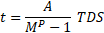
Several parameters define overcurrent relays as the pickup current (IP), the curve type, and the time dial setting (TDS). The operation time (t) is defined by (1) according to the IEC 255 standard [

Two three-phase bolted faults are required for phase relay coordination. The first is near the relay (local maximum fault), while the second is at the end of the protected line (maximum remote fault). The local maximum fault is used to calculate the local operation time (tL), and the maximum remote fault is used to determine the remote operation time (tR).
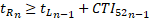
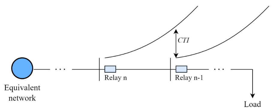
In the system shown in Figure 1, the coordination procedure is frequently initiated at the farthest node from the source. Equation (1) is used to calculate the tL of the relay n-1. Besides, the coordination equation defined by (3) is used to calculate the tR of relay n, where the coordinating time interval (CTI) refers to the time required for the breaker to open the fault and an additional time as a safety criterion.
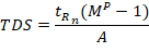
The tRn, maximum remote fault IF, and IP of relay n are used to calculate the minimum time dial setting (TDSn) (4). The local maximum IF and IP are used to calculate the tLn using (1).
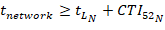
The previous process is repeated up to the relay closest to the source (N). The equation defined by (5) must be satisfied for this relay. In addition, the time defined for the coordination of the equivalent system must be greater than or equal to tL + CTI.
2.1.2 Sequence currents-based adaptive protection approach for DNs with DER (Adaptive Approach I)
The paper presented in [
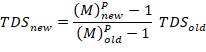
The relay calculates an adaptive TDS when a fault has occurred. Each relay stores the pre-fault positive sequence current, TDS, and IF in the grid-connected mode. Using the value of pre-fault positive sequence current and IF seen in the new operating mode, it adjusts the TDS value to maintain coordination.
Directional overcurrent relay (DOCR) based on negative sequence current is used as backup protection, and the DOCR based on positive sequence current is selected as the primary protection in the ADN. However, the positive sequence fault current is used as the operating quantity for the backup protection for balanced faults.
2.1.3 Superimposed Adaptive Sequence Current Based Microgrid Protection: A New Technique (Adaptive Approach II)
The authors in [
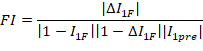
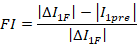
In addition, a new adaptive fault current (IFad) is defined by (9) and calculated at the relay location using the negative-sequence and positive-sequence fault currents and the FI.
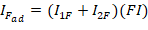
The adaptive fault current is used with the inverse definite minimum time (IDMT) curve as presented in (1) to calculate the tripping time [

2.1.4 Dynamic adaptive protection for distribution systems in Grid-Connected and Island (Adaptive Approach III)
The approach in [
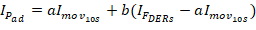
The scheme adjusts the relay sensitivity using the locally measured load current's 10-second moving average window filter (Imov10s). Besides, it considers the maximum fault current supplied by the connected DERs (IFDERs). When any DERs are offline, this fault contribution is not considered. Constant a provides a margin from the non-faulted line load, and b helps the relays maintain sensitivity. These are arbitrarily chosen constants such as a ∈ [1.5, 2] and b ∈ [0, 0.5]. This protection scheme ensures coordination with backup protection.
2.1.5 An adaptive directional current protection scheme for distribution system with DG (Adaptive Approach IV)
An adaptive overcurrent protection scheme based on the fault steady-state component is proposed in [
When a metallic three-phase fault occurs in the system, the measured voltage and current at the relaying point of the faulted line satisfy (12), where UF and IF are the measured voltage and current at the relaying point. ZL is the impedance of the protected line, and α is the per unit length from the relay to the fault.

The setting value of the pickup current of the primary protection (IPad) in the case of a three-phase fault is defined by (13), where Kr is the reliability coefficient.

When the fault current measured (IF) is bigger than IP ad; thus, the protection sends a trip to the corresponding circuit breaker.
2.2 Essential aspects in an adaptive protection approach
Table 1 shows some essential aspects evaluated in each adaptive protection approach presented above. Each aspect is described below:
-
-Consideration of different ADN operation modes, including connected and disconnected from the grid (Connected and islanded mode).
-
-Capability of the proposal to work adequately in radial and meshed systems (Radial and meshed).
-
-Consideration of inverter and synchronous based DERs (DER type).
-
-Requirement of communication systems (Communication scheme).
-
-Identification of the fault direction (Fault direction).
-
-Computation burden required in relay parameter estimation (Computation burden).
-
-Identification of the protective function (Protective function).
| Aspects analyzed | References analyzed | |||
| Appro. I | Appro. II | Appro. III | Appro. IV | |
| Connected and islanded mode | Yes | Yes | Yes | Yes |
| Radial and meshed | Not | Not | Not | Not |
| DERs type | Not | Yes | Yes | Yes |
| Communication schemes | Yes | Yes | Yes | Not |
| Fault direction | Yes | Yes | Not | Yes |
| Computation burden | Yes | Yes | Not | Yes |
| Protective function | 51 | 51 | 50 | 50 |
3. TESTS AND RESULTS
3.1 Test system
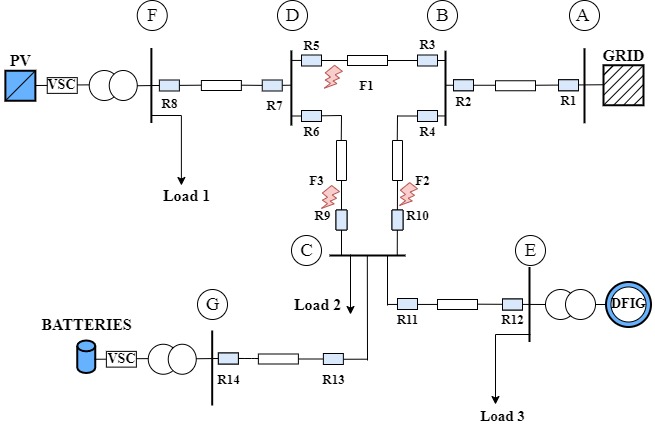
The software used to simulate the ADN is the ATP version of the Electromagnetic Transient Program (EMTP). The test system is a medium voltage (34.5 kV) distribution circuit, depicted in Figure 2. This system has a ring in the central part that connects nodes B, C, and D using three-phase lines. A 20 km length line connects nodes B-D, and nodes B-C, D-C, and C-G are connected with 10 km length lines. The macro-grid is connected to the system by a line with a 10 km length to node B. Similarly, a 10 km line connects the ring system at node D to node F, where PV-based DER (1 MVA) is located. A DFIG-based DER (3 MVA) is coupled by a 10 km length line in node C. Likewise, node G has battery-based energy storage (0.5 MVA). Finally, the system has three distributed loads at nodes F, C, and E, with 1 MVA, 2 MVA, and 1 MVA, respectively, and an inductive power factor of 0.95.
3.2 Testing scenarios
Three operation modes are proposed for the ADN, namely:
-
-Operation mode I (OM I): All sources are on this operation mode.
-
-Operation mode II (OM II): Only the DFIG-based DER is on in this operation mode. The remaining DERs are offline.
-
-Operation mode III (OM III): In this case, only the PV-based DER is on.
3.3 Test results
To compare the performance of the proposed approach concerning the reliability, selectivity, speed, and safety of each approach described in section II (adaptive and conventional), where three faults are simulated, as shown in Figure 2, for each operation mode described in the previous subsection. Thus, the conventional and the adaptive approaches I and II are evaluated using inverse definite minimum time relays. On the other hand, adaptive approaches III and IV are evaluated using instantaneous overcurrent relays.
Tables 2, 3, and 4 show the results obtained for each scenario. Three columns of data are shown for the conventional, adaptive approaches I and II. The first one corresponds to the TDS, the second is the relay operation time of each relay (t), and the third is the time difference (∆T) between tR of the backup protection and tL of the primary protection. Besides, the primary relay is represented as R, and the backup relay as /R for each fault. Therefore, ∆T is not calculated for the primary relay, and it is represented using symbol - in the tables.
| Fault | Relay | Conventional A. | Adaptive A. I | Adaptive A. II | Adaptive A. II | Adaptive A. II | ||||||||||
| TDS | t (s) | ∆T(s) | TDS | t (s) | ∆T(s) | TDS | t (s) | ∆T (s) | IP ad (A) | IF (A) | Trip | IP ad (A) | IF (A) | Trip | ||
| F1 | R5 | 0.047 | 0.084 | - | 0.047 | 0.084 | - | 0.059 | 0.103 | - | 33.18 | 854.34 | YES | 941 | 1255 | YES |
| /R8 | 0.038 | 0.212 | 0.395 | 0.038 | 0.212 | 0.395 | 0.044 | 0.523 | 0.420 | 30.07 | 33.09 | YES | - | - | - | |
| /R9 | 0.148 | 0.212 | 0.127 | 0.148 | 0.212 | 0.127 | 0.150 | 0.211 | 0.105 | 16.48 | 821.81 | YES | - | - | - | |
| R3 | 0.160 | 0.296 | - | 0.160 | 0.296 | - | 0.161 | 0.297 | - | 30.20 | 707.72 | YES | 1356 | 1808 | YES | |
| /R1 | 0.202 | 0.438 | 0.142 | 0.202 | 0.438 | 0.142 | 0.202 | 0.437 | 0.140 | 85.72 | 1433.53 | YES | - | - | - | |
| /R10 | 0.045 | 0.441 | 0.145 | 0.045 | 0.441 | 0.145 | 0.033 | 0.407 | 0.110 | 65.88 | 737.01 | YES | - | - | - | |
| F2 | R4 | 0.149 | 0.202 | - | 0.149 | 0.202 | - | 0.150 | 0.336 | - | 33.18 | 854.34 | YES | 1221 | 1628 | YES |
| /R1 | 0.202 | 0.460 | 0.173 | 0.202 | 0.46 | 0.173 | 0.202 | 0.462 | 0.127 | 85.72 | 1254.36 | YES | - | - | - | |
| /R5 | 0.047 | 0.394 | 0.107 | 0.047 | 0.394 | 0.107 | 0.059 | 0.557 | 0.222 | 33.18 | 297.84 | YES | - | - | - | |
| R10 | 0.045 | 0.103 | - | 0.045 | 0.103 | - | 0.033 | 0.075 | - | 65.89 | 383.04 | YES | 898 | 1198 | YES | |
| /R12 | 0.050 | 0.388 | 0.285 | 0.050 | 0.388 | 0.285 | 0.037 | 0.256 | 0.181 | 56.11 | 96.01 | YES | - | - | - | |
| /R14 | 0.024 | 0.325 | 0.222 | 0.024 | 0.325 | 0.222 | 0.110 | 0.231 | 0.156 | 22.36 | 21.14 | NO | - | - | - | |
| F3 | R6 | 0.144 | 0.248 | - | 0.144 | 0.248 | - | 0.124 | 0.214 | - | 15.02 | 312.62 | YES | 798 | 1064 | YES |
| /R8 | 0.038 | 1.227 | 0.979 | 0.038 | 1.227 | 0.979 | 0.044 | 0.379 | 0.111 | 30.07 | 18.99 | NO | - | - | - | |
| /R3 | 0.160 | 0.392 | 0.144 | 0.160 | 0.392 | 0.144 | 0.161 | 0.399 | 0.131 | 30.20 | 297.21 | YES | - | - | - | |
| R9 | 0.148 | 0.201 | - | 0.148 | 0.201 | - | 0.150 | 0.202 | - | 16.48 | 312.62 | YES | 912 | 1216 | YES | |
| /R12 | 0.050 | 0.388 | 0.187 | 0.050 | 0.388 | 0.187 | 0.037 | 0.302 | 0.100 | 56.11 | 96.01 | YES | - | - | - | |
| /R14 | 0.024 | 0.325 | 0.123 | 0.024 | 0.325 | 0.123 | 0.110 | 0.363 | 0.161 | 22.36 | 21.14 | NO | - | - | - | |
| Fault | Relay | Conventional A. | Adaptive A. I | Adaptive A. II | Adaptive A. II | Adaptive A. II | ||||||||||
| TDS | T (s) | ∆T (s) | TDS | t (s) | ∆T (s) | TDS | t (s) | ∆T (s) | IP ad (A) | IF (A) | Trip | IP ad (A) | IF (A) | Trip | ||
| F1 | R5 | 0.047 | 0.092 | - | 0.040 | 0.084 | - | 0.049 | 0.103 | - | 43.01 | 636.67 | YES | 910 | 1 214 | YES |
| /R9 | 0.148 | 0.223 | 0.132 | 0.124 | 0.212 | 0.127 | 0.150 | 0.211 | 0.108 | 23.19 | 649.32 | YES | - | - | - | |
| R3 | 0.160 | 0.315 | - | 0.137 | 0.296 | - | 0.136 | 0.297 | - | 40.73 | 574.04 | YES | 1 343 | 1 791 | YES | |
| /R1 | 0.202 | 0.469 | 0.174 | 0.177 | 0.438 | 0.142 | 0.175 | 0.437 | 0.110 | 112.95 | 1183.01 | YES | - | - | - | |
| /R10 | 0.045 | 0.121 | -0.175 | 0.16 | 0.441 | 0.145 | 0.146 | 0.407 | 0.110 | 79.38 | 616.05 | YES | - | - | - | |
| F2 | R4 | 0.149 | 0.332 | - | 0.125 | 0.287 | - | 0.145 | 0.336 | - | 78.32 | 967.84 | YES | 1 208 | 1 611 | YES |
| /R1 | 0.202 | 0.446 | 0.159 | 0.177 | 0.460 | 0.170 | 0.175 | 0.462 | 0.127 | 112.95 | 1273.44 | YES | - | - | - | |
| /R5 | 0.047 | 0.117 | -0.170 | 0.040 | 0.394 | 0.109 | 0.049 | 0.557 | 0.222 | 43.01 | 310.34 | YES | - | - | - | |
| R10 | 0.045 | 0.158 | - | 0.160 | 0.103 | - | 0.146 | 0.075 | - | 79.38 | 355.75 | YES | 873 | 1 164 | YES | |
| /R12 | 0.050 | 0.410 | 0.307 | 0.057 | 0.388 | 0.285 | 0.088 | 0.256 | 0.181 | 54.68 | 105.94 | YES | - | - | - | |
| F3 | R6 | 0.144 | 0.252 | - | 0.117 | 0.248 | - | 0.101 | 0.214 | - | 22.41 | 292.15 | YES | 774 | 1 032 | YES |
| /R3 | 0.160 | 0.386 | 0.137 | 0.137 | 0.392 | 0.144 | 0.136 | 0.399 | 0.185 | 40.73 | 309.73 | YES | - | - | - | |
| R9 | 0.148 | 0.275 | - | 0.124 | 0.201 | - | 0.150 | 0.202 | - | 23.19 | 292.33 | YES | 895 | 1 193 | YES | |
| /R12 | 0.050 | 0.410 | 0.208 | 0.057 | 0.388 | 0.187 | 0.088 | 0.302 | 0.100 | 54.68 | 105.94 | YES | - | - | - | |
| Fault | Relay | Conventional A. | Adaptive A. I | Adaptive A. II | Adaptive A. II | Adaptive A. II | ||||||||||
| TDS | T (s) | ∆T (s) | TDS | t (s) | ∆T (s) | TDS | t (s) | ∆T (s) | IP ad (A) | IF (A) | Trip | IP ad (A) | IF (A) | Trip | ||
| F1 | R5 | 0.047 | 0.090 | - | 0.045 | 0.084 | - | 0.055 | 0.103 | - | 40.01 | 669.77 | YES | 931 | 1 241 | YES |
| /R8 | 0.038 | 0.184 | 0.094 | 0.082 | 0.480 | 0.395 | 0.066 | 0.523 | 0.420 | 48.62 | 79.89 | YES | - | - | - | |
| /R9 | 0.148 | 0.228 | 0.138 | 0.093 | 0.212 | 0.127 | 0.093 | 0.211 | 0.105 | 45.82 | 589.84 | YES | - | - | - | |
| R3 | 0.160 | 0.317 | - | 0.153 | 0.296 | - | 0.123 | 0.297 | - | 26.94 | 560.31 | YES | 1 340 | 1 787 | YES | |
| /R1 | 0.202 | 0.468 | 0.151 | 0.172 | 0.438 | 0.142 | 0.170 | 0.437 | 0.140 | 119.32 | 1 195.51 | YES | - | - | - | |
| /R10 | 0.045 | 0.119 | -0.177 | 0.146 | 0.441 | 0.145 | 0.131 | 0.407 | 0.110 | 98.77 | 644.68 | YES | - | - | - | |
| F2 | R4 | 0.149 | 0.330 | - | 0.138 | 0.287 | - | 0.159 | 0.336 | - | 97.94 | 994.91 | YES | 1 206 | 1 608 | YES |
| /R1 | 0.202 | 0.457 | 0.169 | 0.172 | 0.460 | 0.173 | 0.170 | 0.462 | 0.127 | 119.32 | 1 282.83 | YES | - | - | - | |
| /R5 | 0.047 | 0.120 | -0.167 | 0.045 | 0.394 | 0.107 | 0.055 | 0.557 | 0.222 | 29.81 | 294.05 | YES | - | - | - | |
| R10 | 0.045 | 0.169 | - | 0.146 | 0.103 | - | 0.131 | 0.075 | - | 98.77 | 305.01 | YES | 857 | 1 142 | YES | |
| F3 | R6 | 0.144 | 0.241 | - | 0.124 | 0.248 | - | 0.104 | 0.214 | - | 45.54 | 350.16 | YES | 792 | 1 057 | YES |
| /R8 | 0.038 | 0.198 | -0.050 | 0.082 | 1.227 | 0.979 | 0.395 | 0.379 | 0.111 | 38.45 | 71.75 | YES | - | - | - | |
| /R3 | 0.160 | 0.394 | 0.145 | 0.153 | 0.392 | 0.144 | 0.297 | 0.399 | 0.131 | 26.94 | 293.38 | YES | - | - | - | |
| R9 | 0.148 | 0.262 | - | 0.093 | 0.201 | - | 0.093 | 0.202 | - | 45.82 | 350.28 | YES | 880 | 1 173 | YES | |
Similarly, the results for adaptive approaches III and IV are presented in three columns; the first corresponds to the calculated IP ad value, the second is the IF value, and the third indicates the presence of a trip signal.
4. DISCUSSION
In the case of operation mode, I, Table 2 shows that conventional and adaptive approach I present the same TDS and operation time since the IP and IF positive sequence is the same for both approaches, and it is used for coordination purposes. On the other hand, the adaptive approach II presents a difference in TDS and operation time because it used an adaptive fault current IF ad defined by (9).
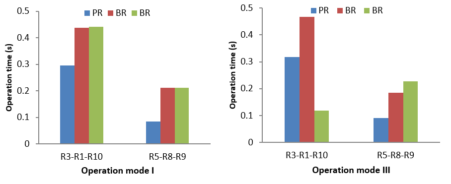
The conventional approach kee ps the IP and TDS fixed for each operation mode. Tables 3 and 4, and Figure 3 show that protection coordination is lost for this approach and some ∆T values are below CTI. Even on some occasions, the backup protections trip faster than the primary protections, indicating a negative ∆T. This can be seen highlighted in the ∆T column of the conventional schematic in Tables 2 and 3.
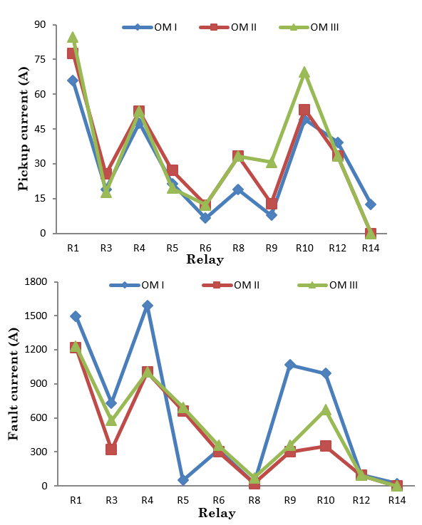
When a DER is disconnected, there are variations in IP and IF as shown in Figure 4. Considering that overcurrent relay operating time depends on the magnitude of the IF, it may increase or decrease in some relays. Thus, the loss of coordination is mainly due to the change in the system operating mode.
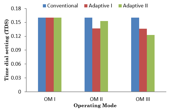
On the other hand, adaptive approaches I and II do not have a fixed value of IP and TDS, since these values depend directly on the operation mode. Tables 3 and 4 show that for each operation mode and different faults, the ∆T is above the CTI. Comparing the R3 settings for F1, it can be seen in Tables 2, 3, 4, and Figure 5 that these values change for each operation mode. Therefore, the adaptive adjustments proposed in these schemes maintain the coordination between protections.
The adaptive approach III uses communication-based coordination [
Finally, the adaptive approach IV is evaluated for the primary protection; the backup protection is not analyzed and indicated using symbol - in tables. The proposed protection scheme calculates the IP according to the current system operation mode and fault type, so that selective fault clearance can be guaranteed. For this approach, faults are simulated at the midpoint of the line. As a result, Tables 2, 3, and 4 show that the primary protections send a trip signal for all faults in the different operating modes. It can be seen that IP is below the value of IF, sending a trip signal to the breaker, clearing the fault a few cycles after it occurs.
5. CONCLUSIONS
An ADN has different operating modes depending on line contingencies, primary energy resource availability, or DERs connection/disconnection. Consequently, the conventional approach does not guarantee overcurrent relay coordination. Therefore, a robust adaptive protection approach must satisfy the reliability, selectivity, speed, economy, and safety criteria for connected and islanded mode, radial and meshed, and inverter and synchronous based DERs. In addition, the proposed algorithms must reduce their computation burden and work with the most negligible communication infrastructure.
Adaptive approaches I and II can provide a solution to coordination with calculating TDS and (IP) for each operation mode. However, these schemes use adaptive parameters estimated using the fault voltages and currents. As a result, it conduces to unacceptable delaying in the trip signal in most cases. In the case of approach III, the estimation of the IP ad presents problems in detecting faults in relays close to the DERs. On the other hand, this approach requires communication infrastructure, making the proposed scheme expensive and vulnerable to cyber-attacks. Likewise, approach IV presents an adequate performance without communication infrastructure but has a long time to detect the fault.
Finally, and as noticed, adequate ADN protection is a challenge; then, several techniques and application strategies have to be proposed shortly, where the fault identification and location strategies have to be analyzed.
6. ACKNOWLEDGMENTS AND FUNDING
This paper is a result of project 6-20-6 funded by the Universidad Tecnológica de Pereira (UTP), and the project identified as contract 774-2020 (Integra2023), funded by the Colombian Ministry of Science, Technology, and Innovation (Minciencias).
CONFLICTS OF INTEREST
All the authors declare no conflict of financial, professional, or personal interests that inappropriately influences the results and the interpretations here presented.
AUTHOR CONTRIBUTIONS
B Grisales-Soto: Conceptualize, conduct the study, and manuscript preparation.
S. Pérez-Londoño: Conceptualize, verify the analytical methods, and manuscript editing.
J Mora-Flórez: Design and conduct the study.
7. REFERENCES
- arrow_upward [1] M. Zeyringer, J. Price, B. Fais, P.-H. Li, and E. Sharp, “Designing low-carbon power systems for Great Britain in 2050 that are robust to the spatiotemporal and inter-annual variability of weather,” Nat Energy, vol. 3, no. 5, pp. 395–403, May 2018, https://doi.org/10.1038/s41560-018-0128-x
- arrow_upward [2] J. McDonald, “Adaptive intelligent power systems: Active distribution networks,” Energy Policy, vol. 36, no. 12, pp. 4346–4351, Dec. 2008, https://doi.org/10.1016/j.enpol.2008.09.038
- arrow_upward [3] P. P. Barker and R. W. de Mello, “Determining the impact of distributed generation on power systems. I. Radial distribution systems,” in 2000 Power Engineering Society Summer Meeting (Cat. No.00CH37134), Aug. 2000, vol. 3, pp. 1645–1656. https://doi.org/10.1109/PESS.2000.868775
- arrow_upward [4] S. Sarangi, B. K. Sahu, and P. K. Rout, “Review of distributed generator integrated AC microgrid protection: issues, strategies, and future trends,” Int J Energy Res, vol. 45, no. 10, pp. 14117–14144, Aug. 2021, https://doi.org/10.1002/er.6689
- arrow_upward [5] A. Hooshyar and R. Iravani, “Microgrid Protection,” in Proceedings of the IEEE, vol. 105, no. 7, pp. 1332–1353, Jul. 2017, https://doi.org/10.1109/JPROC.2017.2669342
- arrow_upward [6] J. D. Garzón-Hidalgo and A. J. Saavedra-Montes, “Una metodología de diseño de micro redes para zonas no interconectadas de Colombia,” TecnoLógicas, vol. 20, no. 39, pp. 39–53, May 2017, https://doi.org/10.22430/22565337.687
- arrow_upward [7] M. Usama et al., “A Comprehensive Review on Protection Strategies to Mitigate the Impact of Renewable Energy Sources on Interconnected Distribution Networks,” IEEE Access, vol. 9, pp. 35740–35765, Feb. 2021, https://doi.org/10.1109/ACCESS.2021.3061919
- arrow_upward [8] G. Kaur, A. Prakash, and K. U. Rao, “A critical review of Microgrid adaptive protection techniques with distributed generation,” Renewable Energy Focus, vol. 39, pp. 99–109, Dec. 2021, https://doi.org/10.1016/j.ref.2021.07.005
- arrow_upward [9] H. Khalid and A. Shobole, “Existing Developments in Adaptive Smart Grid Protection: A Review,” Electric Power Systems Research, vol. 191, p. 106901, Feb. 2021, https://doi.org/10.1016/j.epsr.2020.106901
- arrow_upward [10] P. H. A. Barra, D. V. Coury, and R. A. S. Fernandes, “A survey on adaptive protection of microgrids and distribution systems with distributed generators,” Renewable and Sustainable Energy Reviews, vol. 118, p. 109524, Feb. 2020, https://doi.org/10.1016/j.rser.2019.109524
- arrow_upward [11] J. Pinheiro Nascimento, N. Silva Dantas Brito, and B. Alencar de Souza, “Proposition of an Adaptive Protection Scheme for Distribution Systems with Distributed Generation,” IEEE Latin America Transactions, vol. 16, no. 5, pp. 1439–1444, May 2018, https://doi.org/10.1109/TLA.2018.8408439
- arrow_upward [12] M. Singh, T. Vishnuvardhan, and S. G. Srivani, “Adaptive protection coordination scheme for power networks under penetration of distributed energy resources,” IET Generation, Transmission & Distribution, vol. 10, no. 15, pp. 3919–3929, Nov. 2016, https://doi.org/10.1049/iet-gtd.2016.0614
- arrow_upward [13] J. A. Montoya-Arias, O. A. Tobar-Rosero, G. D. Zapata-Madrigal, and R. García-Sierra, “Algoritmo adaptativo para protecciones de sobrecorriente en el caso de estudio IEEE9,” TecnoLógicas, vol. 22, no. 45, pp. 45–58, May 2019, https://doi.org/10.22430/22565337.1335
- arrow_upward [14] J. P. Nascimento, N. S. D. Brito, and B. A. Souza, “An adaptive overcurrent protection system applied to distribution systems,” Computers & Electrical Engineering, vol. 81, p. 106545, Jan. 2020, https://doi.org/10.1016/j.compeleceng.2019.106545
- arrow_upward [15] P. Naveen and P. Jena, “Adaptive Protection Scheme for Microgrid With Multiple Point of Common Couplings,” in IEEE Syst J, vol. 15, no. 4, pp. 5618–5629, Dec. 2021, https://doi.org/10.1109/JSYST.2020.3039881
- arrow_upward [16] F. Coffele, C. Booth, and A. Dyśko, “An Adaptive Overcurrent Protection Scheme for Distribution Networks,” IEEE Transactions on Power Delivery, vol. 30, no. 2, pp. 561–568, Apr. 2015, https://doi.org/10.1109/TPWRD.2013.2294879
- arrow_upward [17] H. Muda and P. Jena, “Sequence currents based adaptive protection approach for DNs with distributed energy resources,” IET Generation, Transmission & Distribution, vol. 11, no. 1, pp. 154–165, Jan. 2017, https://doi.org/10.1049/iet-gtd.2016.0727
- arrow_upward [18] H. Muda and P. Jena, “Superimposed Adaptive Sequence Current Based Microgrid Protection: A New Technique,” IEEE Transactions on Power Delivery, vol. 32, no. 2, pp. 757–767, Apr. 2017, https://doi.org/10.1109/TPWRD.2016.2601921
- arrow_upward [19] R. Jain, D. L. Lubkeman, and S. M. Lukic, “Dynamic Adaptive Protection for Distribution Systems in Grid-Connected and Islanded Modes,” IEEE Transactions on Power Delivery, vol. 34, no. 1, pp. 281–289, Feb. 2019, https://doi.org/10.1109/TPWRD.2018.2884705
- arrow_upward [20] S. A. Hosseini, S. H. H. Sadeghi, and A. Nasiri, “Decentralized Adaptive Protection Coordination Based on Agents Social Activities for Microgrids With Topological and Operational Uncertainties,” IEEE Trans Ind Appl, vol. 57, no. 1, pp. 702–713, Jan. 2021, https://doi.org/10.1109/TIA.2020.3028351
- arrow_upward [21] S. Baloch, S. S. Samsani, and M. S. Muhammad, “Fault Protection in Microgrid Using Wavelet Multiresolution Analysis and Data Mining,” IEEE Access, vol. 9, pp. 86382–86391, Jun. 2021, https://doi.org/10.1109/ACCESS.2021.3088900
- arrow_upward [22] S. Baloch and M. S. Muhammad, “An Intelligent Data Mining-Based Fault Detection and Classification Strategy for Microgrid,” IEEE Access, vol. 9, pp. 22470–22479, Feb. 2021, https://ieeexplore.ieee.org/document/9344594
- arrow_upward [23] R. Tiwari, R. K. Singh, and N. K. Choudhary, “Coordination of dual setting overcurrent relays in microgrid with optimally determined relay characteristics for dual operating modes,” Protection and Control of Modern Power Systems, vol. 7, no. 1, p. 6, Feb. 2022, https://doi.org/10.1186/s41601-022-00226-1
- arrow_upward [24] S. A. F. Asl, M. Gandomkar, and J. Nikoukar, “Optimal protection coordination in the micro-grid including inverter-based distributed generations and energy storage system with considering grid-connected and islanded modes,” Electric Power Systems Research, vol. 184, p. 106317, Jul. 2020, https://doi.org/10.1016/j.epsr.2020.106317
- arrow_upward [25] P. Dorosti, M. Moazzami, B. Fani, and P. Siano, “An adaptive protection coordination scheme for microgrids with optimum PV resources,” J Clean Prod, vol. 340, p. 130723, Mar. 2022, https://doi.org/10.1016/j.jclepro.2022.130723
- arrow_upward [26] J. Marín-Quintero, C. Orozco-Henao, W. S. Percybrooks, J. C. Vélez, O. D. Montoya, and W. Gil-González, “Toward an adaptive protection scheme in active distribution networks: Intelligent approach fault detector,” Appl Soft Comput, vol. 98, p. 106839, Jan. 2021, https://doi.org/10.1016/j.asoc.2020.106839
- arrow_upward [27] M.-G. Choi, S.-J. Ahn, J.-H. Choi, S.-M. Cho, and S.-Y. Yun, “Adaptive Protection Method of Distribution Networks Using the Sensitivity Analysis for Changed Network Topologies Based on Base Network Topology,” IEEE Access, vol. 8, pp. 148169–148180, Aug. 2020, https://doi.org/10.1109/ACCESS.2020.3015517
- arrow_upward [28] J. Ma, J. Liu, Z. Deng, S. Wu, and J. S. Thorp, “An adaptive directional current protection scheme for distribution network with DG integration based on fault steady-state component,” International Journal of Electrical Power & Energy Systems, vol. 102, pp. 223–234, Nov. 2018, https://doi.org/10.1016/j.ijepes.2018.04.024
- arrow_upward [29] M. A. Elsadd, T. A. Kawady, A.-M. I. Taalab, and N. I. Elkalashy, “Adaptive optimum coordination of overcurrent relays for deregulated distribution system considering parallel feeders,” Electrical Engineering, vol. 103, no. 3, pp. 1849–1867, Jun. 2021, https://doi.org/10.1007/s00202-020-01187-0
- arrow_upward [30] M. Bakkar, S. Bogarra, F. Córcoles, and J. Iglesias, “Overcurrent protection based on ANNs for smart distribution networks with grid‐connected VSIs,” IET Generation, Transmission & Distribution, vol. 15, no. 7, pp. 1159–1174, Apr. 2021, https://doi.org/10.1049/gtd2.12093
- arrow_upward [31] H. Wan, K. K. Li, and K. P. Wong, “An Adaptive Multiagent Approach to Protection Relay Coordination With Distributed Generators in Industrial Power Distribution System,” IEEE Trans Ind Appl, vol. 46, no. 5, pp. 2118–2124, Sep. 2010, https://doi.org/10.1109/TIA.2010.2059492
- arrow_upward [32] International Electrotechnical Commission, Measuring relays and protection equipment-Part 151: Functional requirements of over/under current protection. International Electrotechnical Commission, 2009, p. 63. [Online]. Available: https://webstore.iec.ch/publication/1166
- arrow_upward [33] IEEE, “IEEE Standard for Interconnection and Interoperability of Distributed EnergyResources with Associated Electric Power Systems Interfaces,” in IEEE Std 1547-2018 (Revision of IEEE Std 1547-2003), pp. 1–138, Apr. 2018, https://doi.org/10.1109/IEEESTD.2018.8332112