Optimal Hierarchical Control of Isolated Microgrids
Control jerárquico-óptimo de microrredes aisladas
 PDF
PDF
Received: March 21, 2022
Accepted: May 20, 2022
Available: May 31, 2022
R. Alzate-Castaño; M. A. Mantilla-Villalobos, “Optimal Hierarchical Control of Isolated Microgrids”, TecnoLógicas, vol. 25, nro. 53, e2358, 2022. https://doi.org/10.22430/22565337.2358
Abstract
The objective of this article is to propose a novel method that uses hierarchical control to efficiently manage power resources in an isolated Direct Current (DC) microgrid. The scope of this paper is limited to a numerical study of the components of the micro-generation system using accurate mathematical models in a commercial simulation tool. The control methodology is based on power sharing by means of a hierarchical topology including several control layers. In particular, the internal control loops that regulate the electrical variables in individual generators are at the bottom of the hierarchy. In addition, the power-sharing technique distributes power at an intermediate level, and it is complemented by a Newton-Raphson optimization algorithm at the top, which aims to minimize the cost function. The cost of the microgrid is defined in terms of investment and maintenance indices. This study analyzes the case of a low-power isolated DC microgrid that combines an array of photovoltaic panels and a battery bank. The most relevant result was the optimization of its generation cost, which was verified using simulations of the control and power circuits. In conclusion, although simple, the proposed technique achieves efficient performance in managing the power resources of this microgrid under environmental disturbances.
Keywords: Hierarchical Control, Economic Dispatch, Renewable Energy Sources, Power Management, CC Microgrid.
Resumen
El objetivo del presente artículo fue proponer un método para realizar la gestión eficiente de recursos energéticos en una microrred aislada en corriente continua, empleando control jerárquico. El alcance del trabajo se limitó a estudios numéricos a través de modelos matemáticos precisos en una herramienta de simulación comercial para los componentes del sistema de microgeneración eléctrica. La metodología del control se basó en el reparto de potencias mediante una topología jerárquica con diferentes capas de control. Específicamente, los lazos de control internos que regulan las variables eléctricas en generadores individuales están en la base de la jerarquía, la técnica de reparto de potencias realiza una distribución de energía a un nivel intermedio y se complementa en un nivel superior por un algoritmo de optimización del tipo Newton-Raphson, minimizando un funcional de costo. Dicho costo de la microrred es definido, a su vez, en términos de índices de inversión y mantenimiento. Asimismo, una microrred CC aislada y de baja potencia, constituida por un arreglo de paneles fotovoltaicos combinados con un banco de baterías, es analizada como caso de estudio. El resultado más importante correspondió con la verificación de la optimización del costo de generación mediante simulaciones para los circuitos de control y potencia. En conclusión, la técnica propuesta verifica, a pesar de su simplicidad, un desempeño eficiente para el manejo de recursos energéticos de la microrred ante perturbaciones del entorno.
Palabras clave: Control Jerárquico, Despacho Económico, Fuentes Renovables, Gestión Energética, Microrred CC.
1. INTRODUCTION
The degrading effects of climate change represent a challenge to preserve environmental sustainability [
Modern electric power systems range from simple distributed generation topologies (microgrids [
On the other hand, the intermittency of renewable sources requires dynamic management rules adapting the appropriate use of available resources. In traditional large-scale generation schemes, this is called economic dispatch [
More specifically, the control of isolated (or islanded) microgrids has become a subject of increasing interest for researchers in recent years, given the intricate problems associated with the erratic behavior of renewable resources. In particular, it is challenging to assure a stable and continuous power flow under environmental variations and changing load conditions. A literature review reveals that a key point to perform operational control in isolated microgrids is the state of charge of battery energy storage systems, as it is addressed by Jiechao et al. in [
The droop control technique is a well-known method to achieve power scheduling on electrical grids being adaptable to a hierarchical structure with several levels of regulation loops. Related works include the classical paper of Guerrero et al. [
Hence, inspired by the developments this paper addresses the formulation and implementation of an optimal dispatch based on hierarchical droop control, over a DC microgrid including renewable resources. The approach presented here is simple but tries to illustrate in-depth the solution to the optimal management of renewable power resources by numerical analyzes performed on a simulated testbench. The paper corresponds to an extended version of the work [
2. THE DC MICROGRID
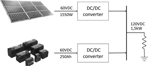
Figure 1 depicts the isolated microgrid selected as a case study. The system includes a series of 5 photovoltaic (PV) panels of 12 VDC / 310 W (for a total power of 1550 W / 60 VDC) in parallel with a bank of 5 batteries of 12 VDC / 250 Ah arranged in series (for a total power of 15000 Wh / 60 VDC), feeding a resistive load demanding 1500 W / 120 VDC. The connection interface between each generator (PV array and batteries) and the DC bus was performed via DC/DC boost power converters. The situation illustrated is inspired by charging units for electric vehicles in Bucaramanga – Colombia (https://www.essa.com.co).
2.1 Open-loop simulation of the microgrid
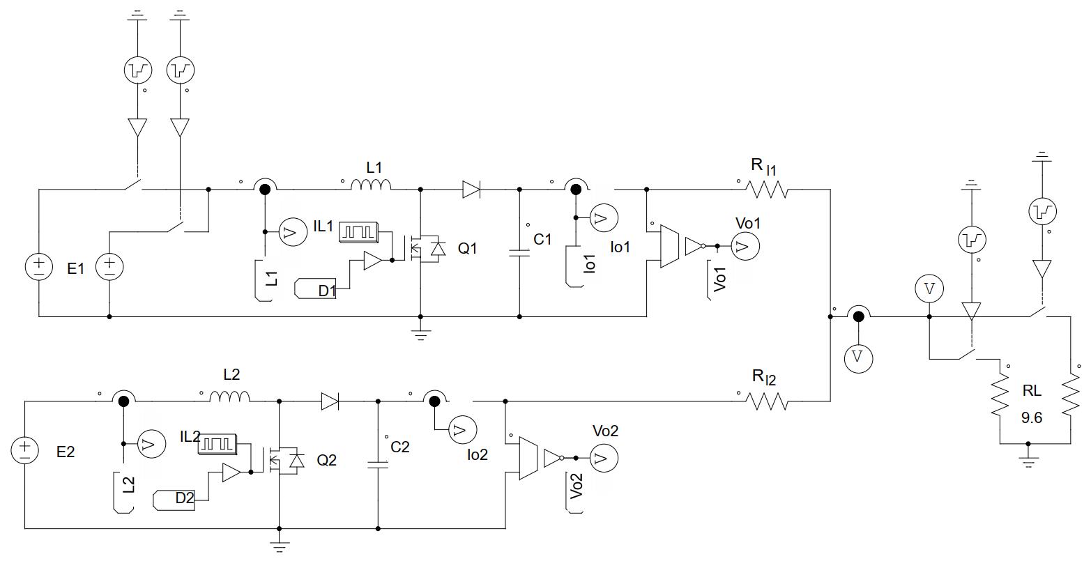
To perform a dynamical analysis of the system, an equivalent circuit for the microgrid was simulated in PSIM (https://powersimtech.com) following the schematic representation shown in Figure 2 and the circuit parameters listed in Table 1.
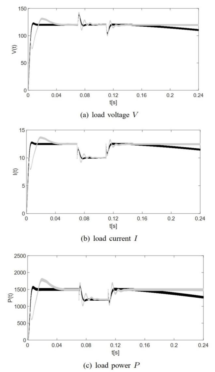
The simulation scenario consisted of a zero initial condition, followed by a change in load nominal value at t = 0.07 s (step variation for RL from 9.6 Ω to 12 Ω), reversed at t = 0.11 s.
In addition, a variation in the supply voltage E1 (from its nominal value of 60 V DC to 55 V DC) was included during the interval t ∈ [0.14, 0.24] s, emulating the decaying lobe of solar radiation after the noon. The corresponding results without control are presented in Figure 3 (dark trace), showing changes in load power (1500 W) as an effect of system disturbances.
3. DROOP CONTROL
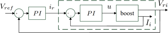
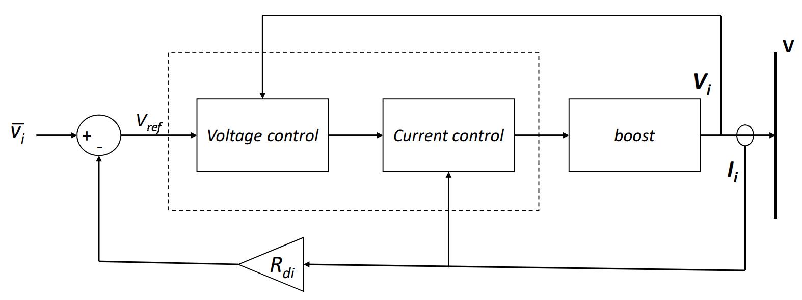
To perform the power-sharing between generators, it is mandatory to achieve first the individual regulation of sources. By following ideas proposed by Utkin [
Source: Created by the authors.
3.1 Power sharing
Once the output values of the perturbed system have been recovered, the droop scheme presented in Figure 5 was configured with Rdi standing for the droop resistance at the i-th generator. The calculation for each Rdi was performed as presented in (1):
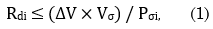
being ∆V the maximum deviation allowed for the DC bus voltage, Pσi = Iσi × Vσ the maximum power delivered to the load by the i-th generator, and Vσ its minimum voltage.
Hence, by assuming fixed proportions of power in (2):

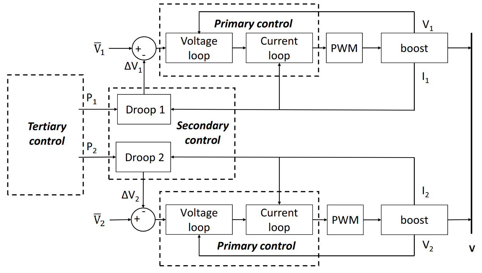
The corresponding droop resistances for the microgrid (taking ∆V = 2 V and Vσ = 118 V) are: Rd1 = 0.262 Ω and Rd2 = 0.393Ω. The hierarchic structure performing the control is illustrated in Figure 6 by a block diagram including the following levels: primary control (internal loops of the converter); secondary control (adjustment given by the droop resistance) and tertiary control (power references for the lower levels). After performing simulations in PSIM for that scheme, the results presented in Figure 7 (dark trace) allow verifying the power-sharing between the PV array and the battery bank according to proportions selected in (2).
4. OPTIMAL MANAGEMENT OF RESOURCES
The results presented so far are not considering generation costs. In general, many authors consider renewable energy power as free and then as a non-dispatchable resource. However, it is possible to assign ponderation rules allowing weighted contributions for generators attending a given demand. The simplest rule is to assign the whole power available, but what about if there are several sources generating power at the same time? and how to proceed in order to mix them properly?
Based on cost models proposed by Hoogwijk in [14], it is possible to define generation costs in renewable sources by (3):

being α the annuity factor, I the investment cost per unit power P installed, and M the maintenance cost per unit power P installed. In particular, employing the information provided by IRENA (https://www.irena.org) on statistics for the year 2021, the cost functions for the PV array and the battery bank were constructed by coefficients listed in Table 2, estimating a total generation cost of the microgrid as in (4):

Further details about these calculations are given in [32] and references therein.
4.1 The optimization problem
To operate the microgrid at the lowest cost, the combination of P1 and P2allowing the minimum of (4) is required, subjected to restriction (2) under variations on generation power, as it is shown by (5):

Among the several methods available to solve the optimization problem defined in (5), the Newton-Raphson approach proposed by Saadat in [13] was employed in this article. In accordance, by noticing that the total generation cost in (4) has a linear fashion, it is required to employ a quadratic transformation to assure the existence of a minimum (concavity). In particular, we chose the function proposed in (6):

and then minimizing Γ(P1, P2) corresponds to minimize C(P1, P2), as it can be easily shown that Γ ≥ C.
By doing so, the Lagrangian function in (7):

can be minimized by an appropriate selection of the Lagrange multiplier λ, subjected to restrictions defined in (2).
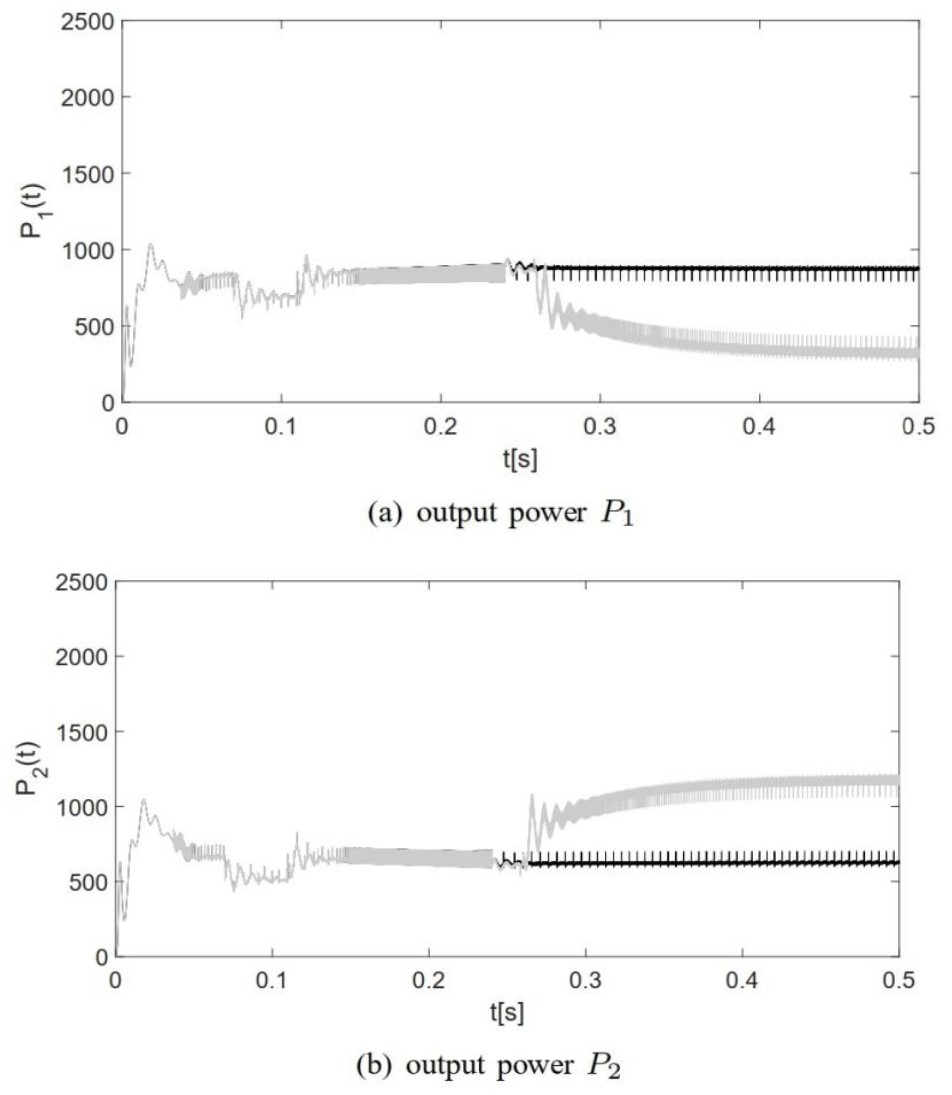
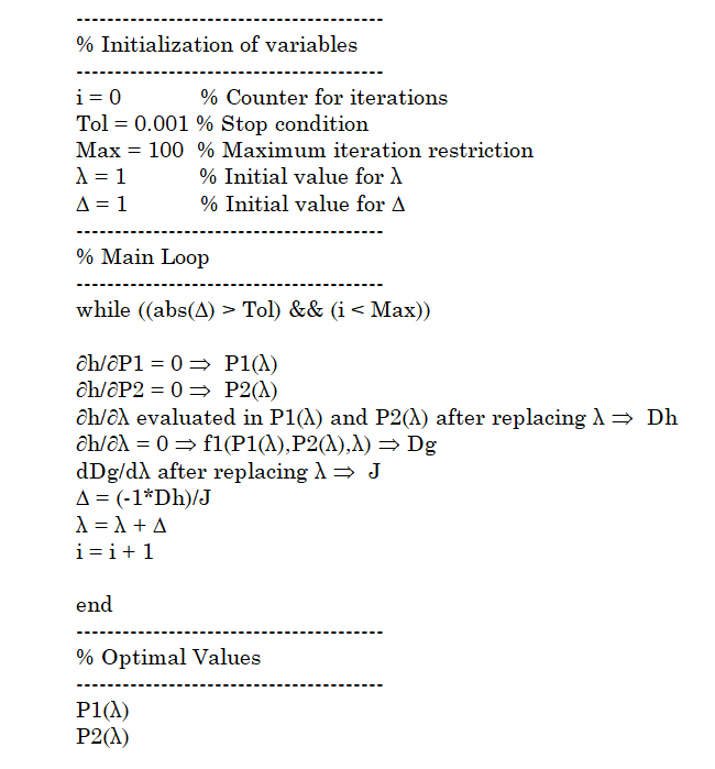
The solution for λ was approximated numerically using a predictor-corrector algorithm programmed in C language and implemented in PSIM with a Simplified C block. An equivalent pseudo-code for the optimization routine is illustrated in Figure 8. The optimized results are contrasted in Figure 7 with the non-optimized power-sharing. As it can be seen (in the gray trace), the steady-state power values are: P1 = 309.53 W and P2 = 1190.5 W, confirming the (easily verifiable) theoretical optimal solution.
Moreover, in Figure 9 a dynamic calculation for the total cost function C(P1, P2) is performed, activating the optimization algorithm at t = 0.24 s and being followed by an alteration in the cost function for the battery bank at t = 0.5 s.
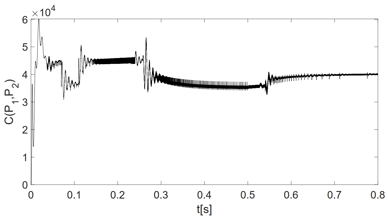
From those results, it is clear that after starting the optimization routine, the calculated total cost tends to be reduced. This fact is consistent with the expected behavior of minimization. Also, there is a small increment after changing the generation cost of the battery bank unveiling the self-adjustment capacity of the proposed approach to adapt energy management to dynamic rules, a situation needed in practice for the appropriate distribution of resources in a real microgrid.
5. CONCLUSIONS
A proposal to perform energy management in isolated DC microgrids employing renewable resources has been addressed. The approach consisted of a hierarchical structure based on droop control driving internal loops of PI classical controllers regulating the electrical variables of DC/DC boost power converters. In order to perform power-sharing and corresponding energy management, it is mandatory to achieve first the appropriate regulation at each generator. In accordance, Figure 3 has shown the dynamic improvement achieved by internal control loops compensating for undesired environmental variations in electrical variables of the system. From there, the controlled system has soft transients with fast recovery for desired reference values. Then, the power proportions can be selected attending to restrictions and cost functions to minimize (optimize) the operation of the microgrid system. For illustration, a simple algorithm based on the Newton-Raphson method was implemented and incorporated into numerical simulations of the grid, showing promising results by dynamic scheduling of power references adapted to environmental conditions. This was reflected in Figure 7 by the change in power trends at each generator, as well as by the reduction in the overall system cost along the time, as depicted in Figure 8.
From there, it is noticeable that despite the increase in generated power under perturbations, the total cost of the optimized mode is always below the cost calculated before activating the optimization algorithm. Ongoing work aims to verify the numerical results presented here but in a real laboratory prototype.
6. ACKNOWLEDGMENTS
Authors would like to acknowledge the financial support of the Universidad Industrial de Santander in Colombia, funding the work presented in this paper under grant code VIE-UIS 2479. Also, the contribution of Mr. Sebastián Benjumea Cerpa in the implementation of the optimization algorithm as part of his degree project.
CONFLICTS OF INTEREST
There are no actual or apparent conflicts of interest by any of the authors related to the manuscript presented.
AUTHOR CONTRIBUTIONS
Ricardo Alzate-Castaño has been in charge of the design and verification by simulation of the internal double-loop control strategy, the droop control strategy, and the minimization rule.
María Alejandra Mantilla-Villalobos was in charge of designing and verifying by simulation of electronic power converters, the photovoltaic array, the battery bank, the system load, and the corresponding disturbances affecting the dynamics of the microgrid.
7. REFERENCES
- arrow_upward [1] J. Gowdy, “Our hunter-gatherer future: Climate change, agriculture and uncivilization”, Futures, vol. 115, p. 102488, Jan. 2020. https://doi.org/10.1016/j.futures.2019.102488
- arrow_upward [2] J. Pardoe; K. Vincent; D. Conway, “How do staff motivation and workplace environment affect capacity of governments to adapt to climate change in developing countries?”, Environ. Sci. Policy, vol. 90, pp. 46 – 53, Dec. 2018. https://doi.org/10.1016/j.envsci.2018.09.020
- arrow_upward [3] W. Krauß; S. Bremer, “The role of place-based narratives of change in climate risk governance”, Clim. Risk Manag., vol. 28, p. 100221, 2020. https://doi.org/10.1016/j.crm.2020.100221
- arrow_upward [4] T. Abbasi; S. Abbasi, “Decarbonization of fossil fuels as a strategy to control global warming”, Renew. Sustain. Energy Rev., vol. 15, no. 4, pp. 1828-1834, May. 2011. https://doi.org/10.1016/j.rser.2010.11.049
- arrow_upward [5] X. Zhou; T. Guo; Y. Ma, “An overview on microgrid technology”, in 2015 IEEE International Conference on Mechatronics and Automation (ICMA), 2015, pp. 76–81. https://doi.org/10.1109/ICMA.2015.7237460
- arrow_upward [6] A. Hirsch; Y. Parag; J. Guerrero, “Microgrids: A review of technologies, key drivers, and outstanding issues”, Renew. Sustain. Energy Rev., vol. 90, pp. 402-411, Jul. 2018. https://doi.org/10.1016/j.rser.2018.03.040
- arrow_upward [7] W. Guacaneme; A. F. Rodríguez; L. M. Gómez; F. Santamaría; C. Trujillo, “Development of a small-scale residential microgrid prototype”, TecnoLogicas, vol. 21, no. 43, pp. 107-125, Sep. 2018. https://doi.org/10.22430/22565337.1065
- arrow_upward [8] J. D. Garzón-Hidalgo; A. J. Saavedra-Montes, “A design methodology of microgrids for non-interconnected zones of Colombia”, TecnoLogicas, vol. 20, no. 39, pp. 39-53, May 2017. https://doi.org/10.22430/22565337.687
- arrow_upward [9] D. López-García; A. Arango-Manrique; S. X. Carvajal-Quintero, “Integration of distributed energy resources in isolated microgrids: the Colombian paradigm”, TecnoLogicas, vol. 21, no. 42, pp. 13-30, May 2018. https://doi.org/10.22430/22565337.774
- arrow_upward [10] M. Lonkar; S. Ponnaluri, “An overview of DC microgrid operation and control”, in IREC2015 The Sixth International Renewable Energy Congress, 2015, pp. 1–6. https://doi.org/10.1109/IREC.2015.7110892
- arrow_upward [11] A. Iovine; G. Damm; E. D. Santis; M. D. D. Benedetto, “Management controller for a DC MicroGrid integrating renewables and storages”, IFAC-PapersOnLine, vol. 50, no. 1, pp. 90-95, Jul. 2017. https://doi.org/10.1016/j.ifacol.2017.08.016
- arrow_upward [12] D. Murillo-Yarce; A. Garcés-Ruiz; A. Escobar-Mejía, “Passivity based control for DC-microgrids with constant power terminals in island mode operation”, Rev. Fac. Ing. Univ. Antioquia, pp. 32-39, Mar. 2018. https://doi.org/10.17533/udea.redin.n86a05
- arrow_upward [13] H. Saadat, Power System Analysis. PSA Publishing LLC, 2011.
- arrow_upward [14] M. M. Hoogwijk, “On the global and regional potential of renewable energy sources”, (Ph.D. Thesis), at Faculteit Scheikunde, Universiteit Utrecht, Mar. 2004. https://www.osti.gov/etdeweb/biblio/20449848
- arrow_upward [15] S. Surender Reddy; P. R. Bijwe; A. R. Abhyankar, “Real-time economic dispatch considering renewable power generation variability and uncertainty over scheduling period”, IEEE Transactions on Power Systems, vol. 9, no. 4, pp. 1440-1451, 2015. https://doi.org/10.1109/JSYST.2014.2325967
- arrow_upward [16] W. D. Giraldo Gómez, “Metodología para la gestión optima de energía en una micro red eléctrica interconectada”, (Tesis de Maestría), Departamento de Energía Eléctrica y Automática, Universidad Nacional de Colombia., 2016.https://repositorio.unal.edu.co/handle/unal/57269
- arrow_upward [17] J. Lv; X. Wang; G. Wang; Y. Song, “Research on Control Strategy of Isolated DC Microgrid Based on SOC of Energy Storage System”, Electronics, vol. 10, no. 7, p. 834, Mar. 2021. https://doi.org/10.3390/electronics10070834
- arrow_upward [18] J. Giraldo; E. Mojica-Nava; N. Quijano, “Synchronization of isolated microgrids with a communication infrastructure using energy storage systems”, Int. J. Electr. Power Energy, vol. 63, pp. 71-82, Dec. 2014. https://doi.org/10.1016/j.ijepes.2014.05.042
- arrow_upward [19] J. Guo; T. Chen; B. Chaudhuri; S. Y. R. Hui, “Stability of Isolated Microgrids with Renewable Generation and Smart Loads”, IEEE Transactions on Sustainable Energy, vol. 11, no. 4, pp. 2845-2854, 2020. https://doi.org/10.1109/TSTE.2020.2980276
- arrow_upward [20] L. Liang; Y. Hou; D. J. Hill, “Enhancing Flexibility of an Islanded Microgrid with Electric Springs”, IEEE Transactions on Smart Grid, vol. 10, no. 1, pp. 899-909, 2019. https://doi.org/10.1109/TSG.2017.2754545
- arrow_upward [21] D. J. Ryan; R. Razzaghi; H. D. Torresan; A. Karimi; B. Bahrani, “Grid-Supporting Battery Energy Storage Systems in Islanded Microgrids: A Data-Driven Control Approach”, IEEE Transactions on Sustainable Energy, vol. 12, no. 2, pp. 834-846, 2021. https://doi.org/10.1109/TSTE.2020.3022362
- arrow_upward [22] J. G. de Matos; F. S. F. e Silva; L. A. d. S. Ribeiro, “Power Control in AC Isolated Microgrids with Renewable Energy Sources and Energy Storage Systems”, IEEE Transactions on Industrial Electronics, vol. 62, no. 6, pp. 3490-3498, 2015. https://doi.org/10.1109/TIE.2014.2367463
- arrow_upward [23] J. M. Guerrero; J. C. Vasquez; J. Matas; L. García de Vicuña; M. Castilla, “Hierarchical control of droop-controlled AC and DC microgrids: A general approach toward standardization”, IEEE Transactions on Industrial Electronics, vol. 58, no. 1, pp. 158-172, 2011. https://doi.org/10.1109/TIE.2010.2066534
- arrow_upward [24] Z. Shuai; J. Fang; F. Ning; Z. J. Shen, “Hierarchical structure and bus voltage control of DC microgrid”, Renew. Sustain. Energy Rev., vol. 82, Part. 3, pp. 3670–3682, Feb. 2018. https://doi.org/10.1016/j.rser.2017.10.096
- arrow_upward [25] W. Li; Y. Gu; H. Yang; W. Sun; Y. Chi; X. He, “Hierarchical control of DC microgrids combining robustness and smartness”, CSEE Journal of Power and Energy Systems, vol. 6, no. 2, pp. 384-393, 2019. https://ieeexplore.ieee.org/stamp/stamp.jsp?arnumber=8779793
- arrow_upward [26] A. A. Hamad; E. F. El-Saadany, “Multi-agent supervisory control for optimal economic dispatch in DC microgrids”, Sustain. Cities Soc., vol. 27, pp. 129-136, Nov. 2016. https://doi.org/10.1016/j.scs.2016.02.016
- arrow_upward [27] W. Gil- González; O. D. Montoya; E. Holguín; A. Garces; L. F. Grisales-Noreña, “Economic dispatch of energy storage systems in DC microgrids employing a semidefinite programming model”, J. Energy Storage., vol. 21, pp. 1-8, Feb. 2019. https://doi.org/10.1016/j.est.2018.10.025
- arrow_upward [28] C. Li; F. de Bosio; F. Chen; S. K. Chaudhary; J. C. Vasquez; J. M. Guerrero, “Economic dispatch for operating cost minimization under real-time pricing in droop-controlled DC microgrid”, IEEE Journal of Emerging and Selected Topics in Power Electronics, vol. 5, no. 1, pp. 587–595, 2017. https://doi.org/10.1109/JESTPE.2016.2634026
- arrow_upward [29] R. Alzate; M. Mantilla, “Proposal for the optimal management of a DC microgrid”, X International Symposium on Electric Power Quality (SICEL 2021). Pereira - Colombia. October 2021.
- arrow_upward [30] V. Utkin; J. Guldner; J. Shi, Sliding Mode Control in Electromechanical Systems. Taylor & Francis, 1999.
- arrow_upward [31] D. C. Hernández Malaver; K. J. Muñoz Galvis, “Control droop de una microrred simple”, (Trabajo de grado), Facultad de Ingenierías Fisicomecánicas, Universidad Industrial de Santander. Bucaramanga, 2019. http://tangara.uis.edu.co/biblioweb/tesis/2019/178062.pdf
- arrow_upward [32] D. M. Hernández Vargas, “Despacho económico y su aplicación en microrredes eléctricas”, (Trabajo de grado), Facultad de Ingenierías Fisicomecánicas, Universidad Industrial de Santander. Bucaramanga, 2019. http://tangara.uis.edu.co/biblioweb/tesis/2019/175927.pdf