Computational comparison of AC and DC motors to hydrodynamic changes in marine fishing vessels
Comparación computacional de motores AC y DC ante cambios hidrodinámicos en embarcaciones marítimas pesqueras
 PDF
PDF
Received: July 01, 2022
Accepted: February 23, 2023
Available: March 22, 2023
Y. L. Correa, I. F. Muñoz, F. Franco Obando, M. Bueno Lopez, “Computational comparison of AC and DC motors to hydrodynamic changes in marine fishing vessels,”TecnoLógicas", vol. 26, nro. 56, e2442, 2023 https://doi.org/10.22430/22565337.2442
Highlights
Abstract
The objective of this article is to make a comparison in a computational environment between an alternating current motor and a direct current motor is made for dynamic variations in the propulsion of an artisanal fishing boat. Initially, the boat was simulated in the Maxsurf software to obtain the dynamic behaviors for pitching, rolling, yawing, and heave motions with wind and wave perturbations for a Pierson Moskowitz spectrum. Subsequently, the motors are selected and in Matlab/Simulink software and a torque behavior required by the vessel to act on the resistance presented in each dynamic motion is proposed. This allows for analyzing the required mechanical and electrical conditions, using the curves obtained in the simulation. Finally, it is concluded that taking into account the criteria of torque, power, speed, and current, the results obtained show that the DC motor is more efficient than the three-phase AC motor for artisanal fishing vessel applications. In addition, the two motors require greater effort to overcome the disturbance related to the rolling motion in the steady-state, while in the transient state the DC motor requires a higher starting torque and the AC motor presents oscillations, which are undesirable disturbances because they produce instability in the electrical system. Additionally, it is important to take into account the energy source that feeds the motors, which can be alternating current or direct current.
Keywords: Pitching motion, yawing motion, rolling motion, wave motion, and hydrodynamic changes
Resumen
El objetivo de este artículo fue realizar la comparación en un ambiente computacional entre un motor de corriente alterna y un motor de corriente continua ante variaciones dinámicas en la propulsión de una embarcación marítima de pesca artesanal. Inicialmente, se simuló la embarcación en el software Maxsurf con el objetivo de obtener los comportamientos dinámicos para los movimientos de cabeceo, balanceo, guiñada y oleaje con perturbaciones de viento y ola para un espectro de Pierson-Moskowitz. Posteriormente, se seleccionaron los motores en el software Matlab/Simulink, donde se propone un comportamiento de torque requerido por la embarcación para actuar ante la resistencia presentada en cada movimiento dinámico. Esto permitió analizar las condiciones mecánicas y eléctricas requeridas mediante las curvas obtenidas en la simulación. Finalmente, teniendo en cuenta los criterios de torque, potencia, velocidad, y corriente, los resultados obtenidos mostraron que el motor DC presenta mayor eficiencia que el motor AC trifásico para aplicaciones de buques de pesca artesanal. Además, se evidenció que los dos motores requieren mayor esfuerzo para vencer la perturbación relacionada al movimiento de balanceo en estado estable, mientras que, en el estado transitorio, el motor DC requiere un par de arranque mayor y el motor AC presenta oscilaciones, las cuales son perturbaciones indeseables debido a que producen inestabilidad en el sistema eléctrico. Es importante tener en cuenta la fuente energética que alimenta los motores que pueden ser de corriente alterna o corriente continua.
Palabras clave: Cambios hidrodinámicos, movimientos de balanceo y oleaje, movimientos de cabeceo, movimientos de guiñada
1. INTRODUCTION
In the last fifty years, maritime transport has gained great importance [
The International Maritime Organization (IMO) estimates that CO2 emissions from international shipping grew to 1056 million tons in 2018 (an increase of 9.3% over 2012), and an increase of between 90% and 130% of emissions is projected by 2050, taking 2008 data as a baseline [
As a solution to this problem, the use of solar energy on ships is proposed to reduce fuel consumption and greenhouse emissions [
The use of these new energy technologies for boats implies that the propulsion system also changes [
In the literature, some investigations compare DC motors and AC motors for different research fields. In [
Similarly, in [
In [
Regarding the comparisons made for electric motors with AC and DC in transportation applications, [
In the context of marine applications, [
The selection of the right engine for the propulsion of marine vessels is a fundamental decision because a poor choice can negatively affect the performance of the vessel, costs can be increased, safety and reliability can be decreased, generating overheating, and causing the propeller to lose efficiency [
Some studies show that running the engine in marine applications with a speed independent of frequency saves fuel consumption compared to fixed speed systems because the engine speed can decrease when the vessel load is low. Additionally, when AC power systems are replaced by DC power systems, the number of converters and dead weight are reduced, and efficiency is increased [
The objective of the article is to make a comparison between a three-phase asynchronous motor and a DC motor with independent excitation in the propulsion of a maritime fishing vessel using computational tools. For this, changes in the hydrodynamic behavior are modeled in the Maxsurf software in different wave and swell conditions, with roll, pitch, and yaw movements. To select the propeller, it is taken into account that a vessel for fishing applications has distinctive characteristics in speed, maneuvering, construction, and storage [
2. METHODOLOGY ASPECTS
The displacement operations of a vessel in the water induce movements of 6 degrees of freedom [
Figure 1 presents each of the stages proposed to make the comparison between 2 electric motors to propel fishing boats.
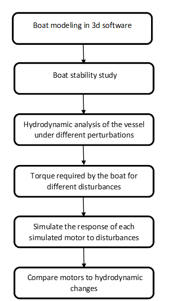
2.1 Vessel design
The comparison between DC and AC motors will be evaluated for an application in the propulsion system of a fishing vessel. For this, it is necessary to know the dynamic behavior of the vessel, which is affected by the weight of the vessel, the speed, the disturbances due to the change in the sea waves, and variations in wind speed. In this way, the engine must respond to different boat conditions.
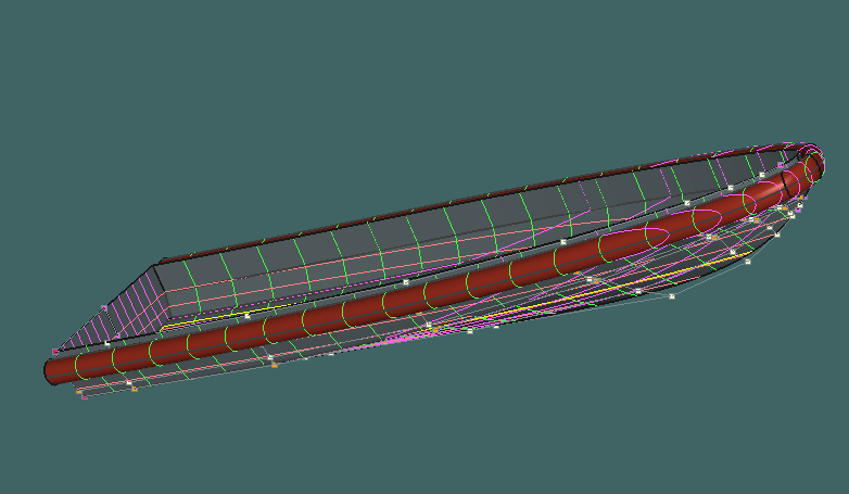
To carry out studies of dynamic behavior it is essential to develop a three-dimensional model of the boat. The model of the fishing vessel was taken from [
2.2 Boat stability study
With the three-dimensional model of the vessel, a stability study or equilibrium test was carried out, where parameters such as the " thread ship", which is the weight of the hull or actual weight of the vessel when it is finished, were considered, as well as the "dead weight", which refers to the vessel's load or capacity to carry. To identify the stability behavior of the vessel, the Maxsurf stability component was used, where the previously obtained model and the mass distribution shown in Table 1 were added.
| Name | Weight - mass (kg) | Longitudinal center of gravity (m) | Vertical center of gravity (m) |
| Boat hull | 440 | 6 | 0.8 |
| People | 150 | 5 | 1.8 |
| Fishing | 40 | 1.5 | 1.5 |
| Total Load | 670 | ||
| Center of Gravity | 5.507 | 1.066 |
The Maxsurf stability component provided the vessel's center of gravity (1,066m) in the face of an added mass distribution, considering the weight of the boat and its components, as well as the location in length and height of the vessel. These dimensions were taken into account for the specific case study with the data presented in Table 1, for other types of vessels with other dimensions and different applications, this center of gravity may change. Subsequently, Maxsurf Motions Advanced (modeler Advanced and stability components) was used, which allows a hydrodynamic analysis of the vessel under different perturbations and mass distribution.
2.3 Hydrodynamic analysis of the vessel under different perturbations
As a first step, the design of the boat is established in the hydrodynamic analysis program, then the center of gravity value obtained in the stability analysis is added to consider the weight of both the boat and its components, then we proceed to create the locations to which the boat will be exposed; conditions such as boat speed, angles, and spectra or disturbances due to sea waves and wind speed are considered.
For this analysis a bridge location was considered where the vessel is steered or handled and it was located at the rear due to the characteristics of a fishing boat, the analysis was executed for an average speed of 8 knots with the center of gravity of 1. 066m, heading angles of 135°,165°,180° and a Pierson-Moskowitz spectrum that defines the wave energy distribution of a fully developed irregular sea surface about wave frequency and wind disturbance [
Once the parameters to which the vessel will be exposed have been defined, an irregular wave surface is calculated with the aid of the Motions program, and the dynamic behavior is simulated for wave, roll, pitch, and yaw motions (see Figure 3).
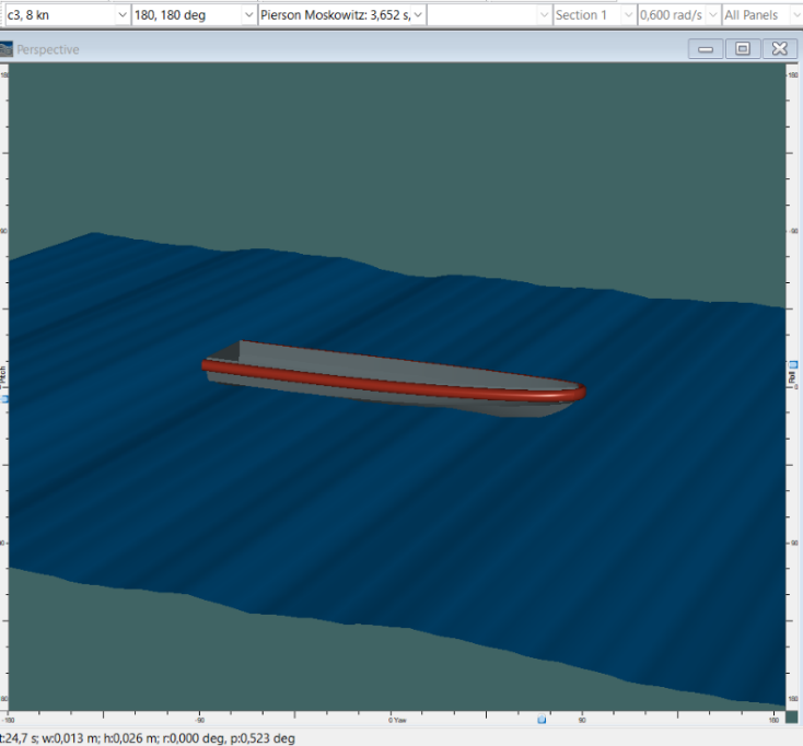
The simulation was performed for a time of 30 seconds in the Maxsurf Motions component. The data provided by the program are presented in units of distance (m) to expose the displacement exerted by the vessel under the different disturbances, with a full load.
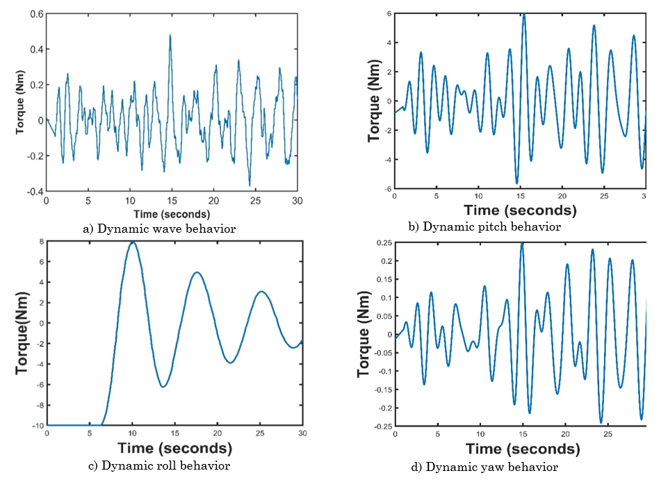
2.4 Torque required by the boat for different disturbances
Taking into account the motion model provided by the Maxsurf software, this study proposes the demand dynamics in units of load torque (Nm) demanded in torque by the vessel, which is the resistance that opposes the movement and is established as the load torque to evaluate the force that each motor must exert to respond to the different dynamic changes. The proposed dynamics inputs in the form of torque to the motor are mapped in Figure 4 with Matlab software. For the study, a load torque behavior is proposed about to the wave motions figure 4 a), for pitching figure 4 b), for roll 4 c) and for yaw 4 d). To excite the motors and analyze their behavior.
2.5 Case study motor response to load torque changes
To determine the necessary capacity of the electric motor required to move the vessel at an average speed of 8 knots, use was made of the Maxsurf resistance component, where the methods of Holtrop and Savitsky [
• Power: 10hp
• Field voltage/armature: 500v / 300v
• RPM: 1500rmp
On the other hand, the alternating current motor has the following parameters:
• Power: 10hp
• Voltage: 460v
• Frequency: 60Hz
• RPM: 1760rpm
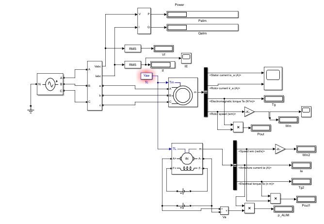
The torque input to the engine are the disturbances of the hydrodynamic behaviors presented in figure 5. The comparison indexes were: torque, speed, current, and power supply this outputs that the simulation produced, these were selected taking into account the literature search [
3. RESULTS AND DISCUSSION
When analyzing the behavior of the boat in relation to changes in wave, yaw, roll and pitch, the curves shown in Figure 6 are obtained, where it is possible to analyze the behavior of torque, current and speed for the two motors studied.
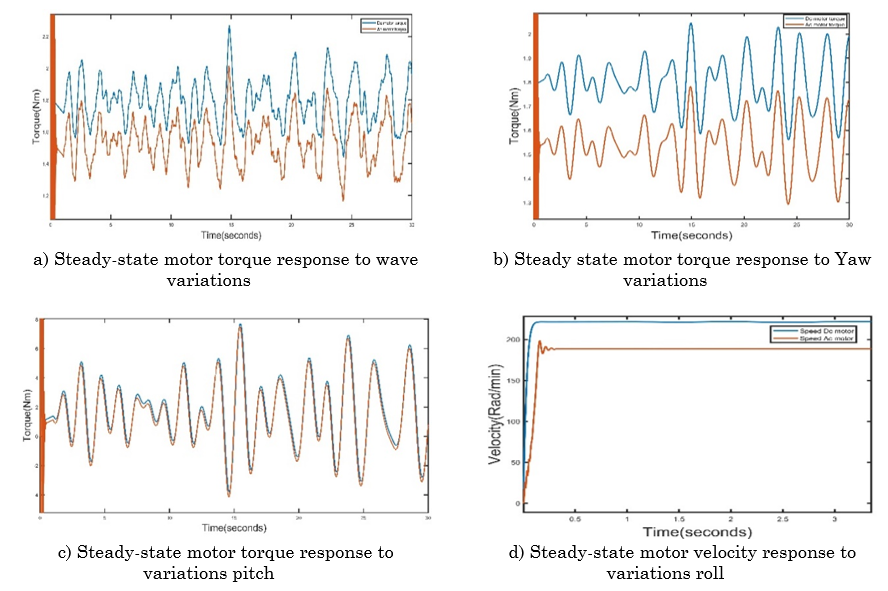
For the torque behavior with respect to the wave Figure 6a), yaw Figure 6b), pitch Figure 6c) and roll Figure 6d), it is observed that the torque of the DC motor is higher than the torque of the AC motor, evidencing that the DC motor generates greater force and greater acceleration. In addition, it is identified that in all cases the two motors respond to the dynamic behavior following the input torque reference. In the surge the torque oscillates between 1.4 Nm and 2.3 Nm, for yaw between 1.4 Nm and 2.1 Nm, in the case of pitch between -4 Nm to 7.8 Nm and in roll between -3.5 Nm and 6 Nm. Referring to the frequency of oscillation that delivers the torque of the two motors, it is evident that in the roll Figure 6d) the wave frequency is low while in the heave Figure 6a) the frequency is high in comparison to the other cases of study.
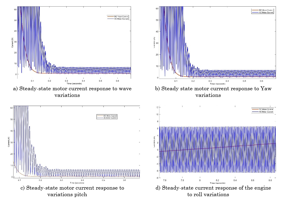
The current curves presented in figures 7a), 7b), 7c) and 7d) correspond to the output of the motors before the torque input required for the surge, yaw, pitch and roll behaviors respectively, from which it is possible to conclude that in steady state the AC motor presents greater oscillations than the DC motor for all the cases of study, where it is reflected that the response of the DC motor is smoother; on the other hand the AC motor needs to deliver more current to perform the same work in comparison to the DC motor. The behavior of the current in the squirrel cage motor oscillates between 0.1 A and 6.512 A and in the permanent magnet motor it is approximately 0.87 A.
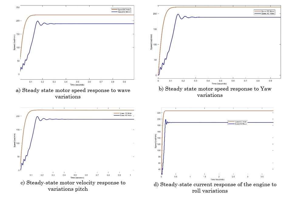
Concerning speed of the motors in the transient state, it is evident that the AC motor presents oscillations before stabilizing for all the required torque inputs as shown in Figures 8a), 8b), 8c) 8d). Similarly in the steady state, it is observed that the speed of the DC motor is higher than that of the AC motor for all the study cases. It is also analyzed that the magnitude of the speed remains constant in a steady state due to its electrical characteristics because the speed in AC motors can only be controlled by an electronic frequency inverter and in DC motors by changing the input voltage.
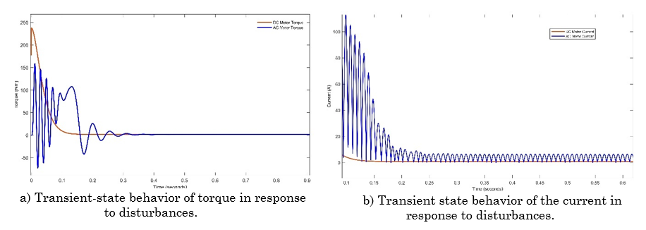
Regarding the transient state in Figure 9a) it is concluded that the DC motor generates a larger value in the starting torque before stabilizing, on the other hand, the torque of the AC motor presents oscillations, which are undesirable disturbances because they produce instability in the electrical system. Now, the current consumption required to perform the same work in the behaviors of the surge, roll, pitch and yaw in the transient state is higher in the AC motor compared to the DC motor, also in the roll and pitch the oscillations are more frequent.
To support the electrical and mechanical analysis presented in the curves, a mathematical analysis of the behavior of the motors is performed, presenting an average of each of the variables to be studied, which are shown in Tables 2-5, to consider all the behavior in steady state for 30 seconds of simulation.
The results shown in the tables confirm that the DC motor presents higher torque and higher speed with a lower current consumption compared to the AC motor. In addition, the variation of each of the variables for the dynamic behavior is observed.
Finally, from the input and output power calculations, the efficiency of the motors presented in Tables 2-5 is obtained, where it is concluded that the DC motor is more efficient than the AC motor in all the cases of study.
| Motor | Voltage (V) | Current (A) | Power supply (W) | Output power (W) | Efficiency (%) | Torque (Nm) | Speed (rad/min) |
| Motor AC | 265.6 | 6.5100 | 332.9460 | 288.8519 | 86.75 | 1.5325 | 188.3727 |
| Motor DC | 500.0 | 0.8023 | 401.4348 | 398.2553 | 99.20 | 1.7986 | 221.3618 |
| Motor | Voltage (V) | Current (A) | Power supply (W) | Output power (W) | Efficiency (%) | Torque (Nm) | Speed (rad/min) |
| Motor AC | 265.6 | 6.5100 | 332.9585 | 288.9380 | 87.77 | 1.5338 | 188.3726 |
| Motor DC | 500.0 | 0.8300 | 401.4979 | 398.4493 | 99.24 | 1.8001 | 221.3603 |
| Motor | Voltage (V) | Current (A) | Power supply (W) | Output power (W) | Efficiency (%) | Torque (Nm) | Speed (rad/min) |
| Motor AC | 265.6 | 6.5170 | 325.6404 | 279.5022 | 85.80 | 1.4912 | 188.3766 |
| Motor DC | 500.0 | 0.7817 | 390.8369 | 384.1156 | 98.00 | 1.7589 | 221.3994 |
| Motor | Voltage (V) | Current (A) | Power supply (W) | Output power (W) | Efficiency (%) | Torque (Nm) | Speed (rad/min) |
| Motor AC | 265.6 | 6.5210 | 323.5128 | 278.9860 | 86.00 | 1.7192 | 188.3682 |
| Motor DC | 500.0 | 0.7192 | 414.7990 | 405.6069 | 97.70 | 1.8422 | 221.4214 |
The main contribution of this investigation is the comparison of two electric motors to the different behavior variations of maritime and fluvial vessels, due to the fact that changes in the behavior of the environment in which a vessel is located can affect the efficiency of the motor, speed, torque, and energy consumption. Additionally, it is sought that people interested in the subject of maritime vessels with electric motors can take this study to consider if the DC motor or the AC motor is the best option, taking into account the technical bases studied in this article to determine the advantages of an engine or another before the same work. In addition, the contribution of this article is very timely because the world is in the process of energy transition where it seeks to replace conventional fuel sources with unconventional energy sources such as clean energy to help reduce the harmful effects generated into the environment by fossil fuels [
4. CONCLUSIONS
It is concluded that for different torques required for the changes or dynamic movements of the boat, the DC motor offers a better performance using less energy to perform the same work, this is evidenced in the efficiency of the motor calculated for the different torque inputs established. In addition, it is observed that the two motors require more torque for the dynamic rolling behavior, this is because the motor needs to make more effort to overcome the resistance that opposes this movement.
For the selection of a motor, it is important to consider the energy sources, because a DC powered motor would provide greater controllability of the vessel given its operating characteristics, which, although it may have high active power losses, it does not dissipate reactive power. On the contrary, motors fed with alternating current require DC/AC converters to adjust their parameters, which generates injection of harmonics that deteriorate performance and decrease efficiency due to the presence of reactive power. Additionally, DC motors do not generate reagents and allow for simpler control, on the contrary, they show considerable copper losses that affect energy efficiency.
As future work, it is proposed that the simulation structure proposed in this article be implemented with prototypes of boats similar to the one established, in laboratories where naval applications with electric motors are studied. In a similar way, it is suggested to carry out tests with prototypes of boats with different characteristics to the proposal that use electric motors where it is possible to change the behavior of the input source.
Additionally, it is proposed to implement this case study in research projects financed by government entities or educational institutions based on research, such as the sustainable rural energization projects (PERS) that exist in Colombia. The results can also be validated in a real prototype that will be developed in Guapi Cauca through the Pacific Econavipesca project: ecosystem for sustainable fishing navigation in the municipality of Guapi, Cauca, where a fishing boat will be built which will be powered by renewable energy sources.
Finally, it is proposed to explore the calculation of the energy demand consumed by the electric motor through other software such as Labvolt and to investigate new strategies that allow optimization of simulation times in different computer programs.
5. ACKNOWLEDGMENTS
This paper is a result of the project Econavipesca del Pacífico, financed by the Swedish International Development Cooperation Agency (SIDA) and developed by Universidad Nacional de Colombia (Colombia), Universidad del Cauca (Colombia), KTH Royal Institute of Technology (Sweden), and Lund University (Sweden).
Jóvenes Investigadores e innovadores en el departamento del Cauca financed the young Yineth Lorena Correa Muñoz.
CONFLICTS OF INTEREST
The authors declare that there is no conflict of interest.
AUTHOR CONTRIBUTIONS
The conceptualization, design and development of the research was in charge of Yineth Lorena Correa. Ivan Felipe Muñoz supported the simulation process. Francisco Franco Obando and Maximiliano Bueno participated in the design of the test protocol and discussion of the results.
6. REFERENCES
- arrow_upward [1] K. Prill, C. Behrendt, M. Szczepanek, and I. Michalska-Pożoga, “A new method of determining energy efficiency operational indicator for specialized ships,” Energies, vol. 13, no. 5, p. 1082, Mar. 2020, https://doi.org/10.3390/en13051082
- arrow_upward [2] S. F. Tie and C. W. Tan, “A review of energy sources and energy management system in electric vehicles,” Renewable and Sustainable Energy Reviews, vol. 20, pp. 82–102, Apr. 2013, https://doi.org/10.1016/j.rser.2012.11.077
- arrow_upward [3] A. Deja, R. Ulewicz, and Y. Kyrychenko, “Analysis and assessment of environmental threats in maritime transport,” Transportation Research Procedia, vol. 55, pp. 1073–1080, 2021, https://doi.org/10.1016/j.trpro.2021.07.078
- arrow_upward [4] F. Diab, H. Lan, and S. Ali, “Novel comparison study between the hybrid renewable energy systems on land and on ship,” Renewable and Sustainable Energy Reviews, vol. 63, pp. 452–463, Sep. 2016, https://doi.org/10.1016/j.rser.2016.05.053
- arrow_upward [5] T. Goh, S. Zhong, B. W. Ang, B. Su, S. H. Ng, and K. H. Chai, “Driving factors of changes in international maritime energy consumption: Microdata evidence 2014–2017,” Energy Policy, vol. 154, p. 112288, Jul. 2021, https://doi.org/10.1016/j.enpol.2021.112288
- arrow_upward [6] L. Goldsworthy and B. Goldsworthy, “Modelling of ship engine exhaust emissions in ports and extensive coastal waters based on terrestrial AIS data - An Australian case study,” Environmental Modelling and Software, vol. 63, pp. 45–60, Jan. 2015, https://doi.org/10.1016/j.envsoft.2014.09.009
- arrow_upward [7] Y. Zhu, S. Zhou, Y. Feng, Z. Hu, and L. Yuan, “Influences of solar energy on the energy efficiency design index for new building ships,” International Journal of Hydrogen Energy, vol. 42, no. 30, pp. 19389–19394, Jul. 2017, https://doi.org/10.1016/j.ijhydene.2017.06.042
- arrow_upward [8] C. C. Chan, "The State of the Art of Electric, Hybrid, and Fuel Cell Vehicles," Proceedings of the IEEE, vol. 95, no. 4, pp. 704-718, April 2007, https://doi.org/10.1109/JPROC.2007.892489
- arrow_upward [9] J. L. Kirtley, A. Banerjee, and S. Englebretson, "Motors for Ship Propulsion," Proceedings of the IEEE, vol. 103, no. 12, pp. 2320-2332, Dec. 2015, https://doi.org/10.1109/JPROC.2015.2487044
- arrow_upward [10] C. Nuchturee, T. Li, and H. Xia, “Energy efficiency of integrated electric propulsion for ships – A review,” Renewable and Sustainable Energy Reviews, vol. 134, p. 110145, Dec. 2020, https://doi.org/10.1016/j.rser.2020.110145
- arrow_upward [11] F. Vargas-Machuca, Maquinas eléctricas rotativas. Lima, Perú, 1990.
- arrow_upward [12] J -R. Riba, C. López-Torres, L. Romeral, and A. Garcia, “Rare-earth-free propulsion motors for electric vehicles: A technology review,” Renewable and Sustainable Energy Reviews, vol. 57, pp. 367–379, May. 2016, https://doi.org/10.1016/j.rser.2015.12.121
- arrow_upward [13] O. F. C. Atalaya, N. Y. H. Ccallo, uis E. R. Vicuña, R. J. C. Ilizarbe, J. A. P. Torres, and J. J. F. R. Rupay, “Experimental Analysis in Alternate Current and Direct Current of the Operating Parameters of a Universal Single-Phase Engine,” Advances in Science, Technology and Engineering Systems Journal, vol. 4, no. 6, pp. 360–370, Jan. 2019, https://doi.org/10.25046/aj040646
- arrow_upward [14] Y. Tanaka, S. Sakama, K. Nakano, and H. Kosodo, “Comparative Study on Dynamic Characteristics of Hydraulic, Pneumatic and Electric Motors,” in ASME/BATH 2013 Symposium on Fluid Power and Motion Control, Oct. 2013, pp. 1–6. https://doi.org/10.1115/FPMC2013-4459
- arrow_upward [15] M. Miyamasu and K. Akatsu, "Efficiency comparison between Brushless dc motor and Brushless AC motor considering driving method and machine design," in IECON 2011 - 37th Annual Conference of the IEEE Industrial Electronics Society, Melbourne, VIC, Australia, Nov. 2011, pp. 1830-1835, https://doi.org/10.1109/IECON.2011.6119584
- arrow_upward [16] K. Selvakumar, S. S. Menon, K. V. Kaushik, and D. Karthikeyan, “Electric Boat Propulsion System Using Multilevel Converter Based on ANN Controller,” International Journal of Recent Technology and Engineering, vol. 8, no. 2S11, pp. 3319–3326, Sep. 2019, https://doi.org/10.35940/ijrte.B1560.0982S1119
- arrow_upward [17] K. Sedef, A. Maheri, A. Daadbin, and M. Yilmaz, "A comparative study of the performance of DC permanent magnet and AC induction motors in urban electric cars," in 2012 2nd International Symposium On Environment Friendly Energies And Applications, Newcastle Upon Tyne, UK, Jun. 2012, pp. 100-105, https://doi.org/10.1109/EFEA.2012.6294077
- arrow_upward [18] R. Lateb, N. Takorabet, F. Meibody-Tabar, A. Mirzaian, J. Enon, and A. Sarribouette, "Performances comparison of induction motors and surface mounted PM motors for POD marine propulsion," in Fourtieth IAS Annual Meeting. Conference Record of the 2005 Industry Applications Conference, 2005, Hong Kong, China, Oct. 2005, vol. 2, pp. 1342-1349, https://doi.org/10.1109/IAS.2005.1518534
- arrow_upward [19] B. Rexroth Corporation, “Electric, Hydraulics, Pneumatics: Evaluating Their Advantages for Automotive Manufacturing Processes,” Bosch Group, IL USA. 2006. https://pdfslide.net/documents/electric-hydraulics-pneumatics-evaluating-their-hydraulics-pneumatics-evaluating.html?page=5
- arrow_upward [20] P. Ghimire, M. Zadeh, J. Thorstensen, and E. Pedersen, "Data-Driven Efficiency Modeling and Analysis of All-Electric Ship Powertrain: A Comparison of Power System Architectures," IEEE Transactions on Transportation Electrification, vol. 8, no. 2, pp. 1930-1943, June 2022, https://doi.org/10.1109/TTE.2021.3123886
- arrow_upward [21] O. Simmonds, “DC: Is it the alternative choice for naval power distribution?,” Journal of Marine Engineering & Technology, vol. 13, no. 3, pp. 37–43, Dec. 2014, https://doi.org/10.1080/20464177.2014.11658120
- arrow_upward [22] P. Ghimire, D. Park, M. K. Zadeh, J. Thorstensen, and E. Pedersen, "Shipboard Electric Power Conversion: System Architecture, Applications, Control, and Challenges [Technology Leaders]," IEEE Electrification Magazine, vol. 7, no. 4, pp. 6-20, Dec. 2019, https://doi.org/10.1109/MELE.2019.2943948
- arrow_upward [23] Y. -k. Son, S. -Y. Lee, and S. -K. Sul, "DC Power System for Fishing Boat," in 2018 IEEE International Conference on Power Electronics, Drives and Energy Systems (PEDES), Chennai, India, Dec. 2018, pp. 1-6, https://doi.org/10.1109/PEDES.2018.8707631
- arrow_upward [24] D. Mulyana, F. Koeshardono, A. Sudradjat, and R. Y. Widiatmoko, “Optimization of B-series propeller geometry dimension to improve traditional fishing ship performance,” IOP Conference Series: Materials Science and Engineering, vol. 830, no. 4, pp. 042035, Apr. 2020, https://doi.org/10.1088/1757-899X/830/4/042035
- arrow_upward [25] T. N. Van, L. Thanh, and N. Natasa, “Measuring propeller pitch based on photogrammetry and CAD,” Manufacturing Technology, vol. 21, no. 5, pp. 706–713, Nov. 2021, https://doi.org/10.21062/mft.2021.070
- arrow_upward [26] M. Tatiana and R. Ordo, “Sistema de generación híbrido basado en fuentes no convencionales de energía para pesca artesanal en el municipio de Guapi, Cauca,” Universidad del Cauca, 2021. http://repositorio.unicauca.edu.co:8080/xmlui/handle/123456789/5543
- arrow_upward [27] J. Rubio Hervas, M. Reyhanoglu, H. Tang, and E. Kayacan, “Nonlinear control of fixed-wing UAVs in presence of stochastic winds,” Communications in Nonlinear Science and Numerical Simulation, vol. 33, pp. 57–69, Apr. 2016, https://doi.org/10.1016/j.cnsns.2015.08.026
- arrow_upward [28] X. Chen et al., “Infrared Ocean Image Simulation Algorithm Based on Pierson–Moskowitz Spectrum and Bidirectional Reflectance Distribution Function,” Photonics, vol. 9, no. 3, p. 166, Mar. 2022, https://doi.org/10.3390/photonics9030166
- arrow_upward [29] R. R. Torres Parra, S. Lonin, “Estudio del espectro de oleaje en el Caribe observado con boyas y su representación en el espectro Jonswap,” Boletín Científico CIOH, no. 25, pp. 8–18, Sep. 2007, https://doi.org/10.26640/01200542.25.8_18
- arrow_upward [30] M. Bilec and C. D. Obreja, “Ship resistance and powering prediction of a fishing vessel,” in IOP Conf Ser Mater Sci Eng, vol. 916, no. 1, p. 012011, Sep. 2020, https://doi.org/10.1088/1757-899X/916/1/012011
- arrow_upward [31] N. A. Maliky, N. P. Putra, M. T. Subarkah, and S. Hidayat, “Prediction of Vessel Dynamic Model Parameters using Computational Fluid Dynamics Simulation,” Advances in Science, Technology and Engineering Systems, vol. 5, no. 6, pp. 926–936, Dec. 2020, https://doi.org/10.25046/aj0506110
- arrow_upward [32] I. Fabregas Claramunt, “Estudio métodos de predicción de resistencia al avance,” (Trabajo fin de grado), Departamento de Ciencia e Ingeniería Náuticas, Universidad Politécnica de Catalunya, Barcelona, 2018.
- arrow_upward [33] W. Zhang, D. Jiang, and P. Li, “Design of Power and Energy System for a Small Garbage Cleaning Ship,” in IOP Conference Series: Earth and Environmental Science, vol. 603, pp. 012046, Nov. 2020, https://doi.org/10.1088/1755-1315/603/1/012046
- arrow_upward [34] Y. Bapodra and U. Rajamanickam2, “A review on Hybrid Electric Vehicle and simulation on Hybrid Electric Vehicle Drivetrain,” in IOP Conference Series: Earth and Environmental Science, vol. 633, p. 012007, Jan. 2021, https://doi.org/10.1088/1755-1315/633/1/012007
- arrow_upward [35] B. N. Abramovich, Y. A. Sychev, and P. A. Kuznetsov, “Modernization of gas-turbine engines with high- frequency induction motors,” IN IOP Conference Series: Materials Science and Engineering, vol. 327, p. 052001, Mar. 2018, https://doi.org/10.1088/1757-899X/327/5/052001
- arrow_upward [36] G. Pleßmann, M. Erdmann, M. Hlusiak, and C. Breyer, “Global Energy Storage Demand for a 100% Renewable Electricity Supply,” Energy Procedia, vol. 46, pp. 22–31, 2014, https://doi.org/10.1016/j.egypro.2014.01.154