Design, Analysis, and Modeling of Curved Photovoltaic Surfaces Using Composite Materials
Diseño, análisis y modelamiento de superficies fotovoltaicas curvas usando materiales compuestos
 PDF
PDF
Received: September 25, 2021
Accepted: May 3, 2022
Available: May 26, 2022
G. Espitia-Mesa; E. Hernández-Pedraza; S. Molina-Tamayo; R. Mejía-Gutiérrez, “Design, analysis, and modeling of curved photovoltaic surfaces using composite materials”, TecnoLógicas, vol. 25, nro. 53, e2171, 2022. https://doi.org/10.22430/22565337.2171
Abstract
Currently, the use of photovoltaic solar energy has increased considerably due to the development of new materials and the ease to produce them, which has significantly reduced its acquisition costs. Most commercial photovoltaic modules have a flat geometry and are manufactured using metal reinforcement plates and glass sheets, which limits their use in irregular surfaces such as roofs and facades (BIPV) and the transportation sector (VIPV). The purpose of this study is to analyze the design implications of curved photovoltaic surfaces using composite materials. Considering operation and maintenance requirements, the most suitable reinforcement and encapsulation materials are selected based on references and experimental tests. It was found that the maximum radius of curvature that a polycrystalline silicon cell with the dimensions of a SunPower C60 model can achieve is 6.51 m for a failure probability lower than 5 %, which allows us to define the maximum curvature that this photovoltaic surface can reach. Additionally, an analytical model of the reinforcement was implemented using macromechanical models in Matlab™, which was validated by the finite element method employing the composite materials module in Ansys®. Therefore, this paper presents a detailed analysis of the shear stresses between the layers and of the deformations generated in the curved solar panel reinforcement. Finally, under the operating conditions assumed here, carbon fiber presents the best structural behavior in the reinforcement material, while epoxy resin exhibits a better performance in the encapsulation material. These results can facilitate the manufacturing of curved photovoltaic surfaces.
Keywords: Solar Energy; Photovoltaic Surfaces; Curved Solar Panel; Building-Integrated Photovoltaics (BIPV); Vehicle-Integrated Photovoltaics (VIPV).
Resumen
Actualmente, el uso de la energía solar fotovoltaica ha aumentado de manera importante a partir del desarrollo de nuevos materiales y la facilidad de producción de los mismos, lo cual ha disminuido significativamente los costos de adquisición. Comercialmente, la mayoría de los módulos fotovoltaicos tienen geometrías planas y se fabrican a partir de placas de refuerzo metálico y láminas de vidrio, lo cual limita su uso en superficies irregulares como techos y fachadas (BIPV) y en el sector del transporte (VIPV). El propósito de este estudio es analizar las implicaciones de diseño de superficies fotovoltaicas con curvatura usando materiales compuestos. Partiendo de la definición de los requerimientos de operación y mantenimiento, se seleccionan los materiales de refuerzo y encapsulado más adecuados a partir de referencias y pruebas experimentales. Se obtiene que el radio de curvatura máximo alcanzado por una celda de silicio policristalina con las dimensiones de la referencia SunPower C60 es de 6,51 m para una probabilidad de falla menor al 5 %, lo que permite definir la curvatura máxima que puede alcanzar la superficie fotovoltaica. También se implementa un modelo analítico del refuerzo usando modelos de macromecánica a través de Matlab™, el cual es validado por el método de los elementos finitos usando el módulo de materiales compuestos de Ansys®. De esta manera, se presenta un análisis detallado de los esfuerzos cortantes entre las capas y de las deformaciones generadas en el refuerzo del panel solar curvo. Finalmente, para las condiciones de operación analizadas, el mejor comportamiento estructural en el material refuerzo lo presenta la fibra de carbono, mientras que, para el material de encapsulado, la resina epóxica presenta un mejor comportamiento. Estos resultados pueden facilitar la fabricación de superficies fotovoltaicas con curvatura.
Palabras clave: Energía Solar; Superficies Fotovoltaicas; Panel Solar Curvo; Fotovoltaica Integrada en Edificios (BIPV); Fotovoltaica Integrada a Vehículos (VIPV).
NOMENCLATURE
E Young Module (MPa)
G Shear Module (MPa)
ν Poisson Modules
Ef Flexure Module of Elasticity (GPa)
σf Maximum bending stress (MPa)
σVM Von Mises Stress (MPa)
σy Yield Strenght (MPa)
t Ply thickness (mm)
ρ Density (kg ⁄ m3)
ε Normal Deformation (mm)
d Displacement (mm)
σ Surface Density (g ⁄ m2)
γ Shear Deformation (mm)
τ Shear Stress (MPa)
Sij Compliance coefficients of the lamina (MPa-1)
δ Directional deformation (mm)
m Mass (kg)
H Hardness (Shore D)
1. INTRODUCTION
This paper corresponds to an extended version of the work presented at WEA 2021, in which the modeling and simulation of the mechanical behavior of photovoltaic surfaces with curvature is proposed, this is achieved by analyzing the deformation capacity of a photovoltaic cell and its influence within the reinforcement [
Nowadays, the trend of energy consumption on the planet is increasing due to the growth of the world’s population and the invention of new electronic devices such as cell phones, vehicles, etc. This fact motivates countries to use non-conventional sources of energy, which are becoming more accessible. Photovoltaic (PV) energy can be considered as one of the Renewable Energies (REs) with higher potential in the future, thanks to its capacity to supply the worldwide energy demand [
1.1. State of the art
The possibility of having adaptable curved solar modules, allows to think on having photovoltaic surfaces for localized energy production, in order not to depend exclusively on solar farms. These localized applications are precisely on roofs based on geodesic shapes [
However, for applications in transportation systems and buildings, it is possible to propose curved geometries that allow a better adaption to the required complex shapes which is further complicated by the configuration of conventional commercial solar panels due to the curved geometry the glass must take. This fact has severe implications in terms of conventional manufacturing. For this reason, it is necessary to explore other manufacturing techniques, in this case, the use of composite materials and its mechanical behavior will be analyzed.
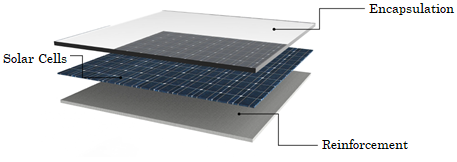
A solar panel is an array of interconnected solar cells, most manufactured of silicon which converts the sun's energy into electricity. Solar cells are assembled in a sandwich arrangement above and below. The material on top of the cell must have good optical properties, this allows solar radiation can be absorbed as easily as possible, this material is called encapsulation. Similarly, the material at the bottom of the cell is called reinforcement, which must guarantee the structural strength. These layers can be seen in Figure 1.
Photoelectric effect presented in solar cells transforms solar radiation into consumable electrical energy and heat, which has a significant negative implication on the overall efficiency of 75.58 % while reflection losses are approximately 6.98 % [
Also, thermo-mechanical studies have been carried out in order to estimate the influence of temperature on the structural capacity of the PV module assembly [
2. METHODOLOGY
Activities related to the design photovoltaic solar surfaces with curvature, must start from the deep knowledge of its operation, the arrangement and relationship of the elements that make it up and working environment in which it will operate [
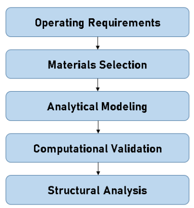
Materials used in manufacturing photovoltaics must guarantee adequate mechanical properties to absorb operating loads and preserve structural integrity of solar cells. These conditions are analyzed through an analytical model which is validated with finite element method. According to the above, it is necessary to establish the operating environment in which the photovoltaic module operates. Design of the photovoltaic module will be performed separately for encapsulation and reinforcement, this fact will allow understanding the structural role of each of them within the PV module assembly, which will generate technical information for decision making in the design process, this will be described in the following sections.
2.1. Operating requirements
Considering the high fragility of silicon solar cells and their low thickness in the order of micrometers, the encapsulated-reinforming arrangement must guarantee a high structural resistance for the operation loads and maintenance of the solar panel. Additionally, the manufacturing of photovoltaic surfaces with curvature causes the cell to take different shapes than the flat one, which causes stresses and deformations. These requirements and conditions will be described in the following subsections.
2.1.1. Loads in photovoltaic surfaces
The purpose of this project is to orient the applications of curved photovoltaic surfaces to the transportation and construction sectors. Although the performance scenarios are different, the maintenance operation is common in both cases, the most critical circumstance being that the photovoltaic module must have the capacity to support the weight of a person without affecting the integrity of the solar cells. Thus, for a 95th percentile, the weight of a Colombian man is approximately 87.9 kg (861.4 N) [
2.1.2. Estimation of the maximum radius of curvature on the cell
Radius of curvature will be based on the ability of the solar cell to deform and take the shape of the panel. Assembling this type of panels, it is necessary to preload the cell so that it adjusts to the shape of the reinforcement. In this way, it is necessary to estimate the maximum deformation that the cell can independently withstand, SunPower C60 cell dimensions will be taken as a reference including silicon properties.
Therefore, a maximum fracture stress is established according to the type of solar cell, the direction of the applied load and the probability of failure. It is important to consider that will be additional loads in system due to the operation, thus, a critical load scenario for solar cell is proposed, with forces in a perpendicular direction, using polycrystalline cells assuming a failure probability of 5 %, which establishes a fracture stress in the order of 10 MPa [
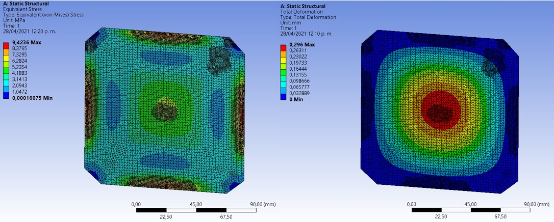
In this way, a load close to 100 N is applied for the purpose of not generating a stress greater than 10 MPa, which generates a stress of 9.4 MPa, a value that is below the permissible stress assumed. Regarding the deformation, a maximum deflection of 0.29 mm in the center was obtained, which establishes a maximum radius of curvature of the cell of 6.51 m from geometric estimations and the structural conditions previously exposed.
2.2. Materials selection
Manufacturing of solar panels using composite materials is based on the scheme shown in Figure 1. Reinforcement is made from the union of fabrics and a matrix material, while the encapsulation is a coating of a layer of translucent material that allows isolating the solar cells from the environment, adhering them to the reinforcement. For both parts it is a handmade process, so the mechanical properties obtained can have great variability between manufacturers, for this reason some properties are referenced from the literature and obtained from experimental tests.
2.2.1 Alternatives for reinforcement’s materials
Based on the requirements, composite materials are an excellent choice for the manufacturing of panel reinforcement. These materials are presented in the form of fabrics, which can be joined by the use of resins. Using these materials is highly dependent on commercial availability. Properties were found for Kevlar, Fiberglass and Carbon Fiber [
| Properties | |||||
| E1 [MPa] | |||||
| E2, E3 [MPa] | |||||
| ν1, ν2 | |||||
| ν3 | |||||
| G12, G13 [MPa] | |||||
| G23 [MPa] | |||||
| t [mm] | |||||
| ρ [kg⁄m3] | |||||
The behavior of this type of materials normally changes according to the orientation of their fibers, for this reason the properties are shown according to their axes, additionally the average thickness per layer and the density are shown.
2.2.2 Flexure test for reinforcement’s materials
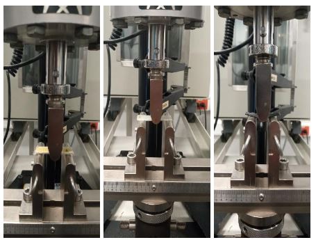
Commercial panels have a metal frame or backsheet that provides additional structural capacity to the glass to support its own weight, which causes bending stresses. In photovoltaic modules made of composite materials, reinforcement must have the ability to maintain its shape without deformation, so a bending test to the fabrics is presented to estimate this behavior, the used set-up is shown in Figure 4.
Source: created by the authors.
These tests were performed using the ASTMD790 standard on a Instron universal machine, model 3366. A total of 15 rectangular specimens were tested for plains of kevlar, carbon fiber, and glass fiber with a surface density of σK=(296 g) ⁄ (m2,) σCF=(198 g)⁄m2 , and σGF=(198 g)⁄m2 respectively. From the bending test we obtained a flexural modulus of elasticity of EK=1.52 GPa, ECF=7.42 GPa and EGF=7.14 GPa, with an impregnation percentage close to 50 % using rigid epoxy resin. The flexure stress vs. strain curves for each of the specimens are shown in Figure 5.
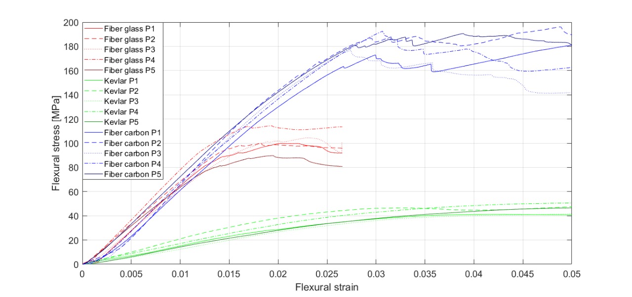
It is observed that the flexural rigidity of carbon fiber and fiberglass are superior to those of Kevlar, which presents high ductility. However, the fracture toughness of the fibers is higher in carbon fiber than in glass fiber, making it the best reinforcement material from the mechanical properties.
2.2.3 Alternatives for encapsulation materials
Functions of encapsulation material in a photovoltaic module is to increase the photon transmission capacity inside the module, also it must be a material resistant to scratching, so hardness is a very important characteristic. From [
Source: created by the authors.
| Properties | ||
| E[MPa] | ||
| ν | ||
| σy [MPa] | ||
| ρ [kg ⁄ m3 ] |
It is observed that the epoxy resin presents better mechanical properties than silicone, which suggests that the solar cell will have greater structural integrity if it is used as an encapsulation material. On the contrary, the use of silicone allows a better photon transfer along the encapsulation material, however due to the low commercial availability this will be discarded, so, in the following sections only the effect of the epoxy resin will be analyzed using the mechanical properties listed above.
2.2.4 Experimental analysis for encapsulation materials
A search in the market is carried out and a total of 3 epoxy resins were identified: Rigid Epoxy Resin, Flexible Epoxy Resin and Ecopoxy Resin. The first two are used in composite laminating applications and the third one is used in optical and encapsulation applications.
Considering that the encapsulation must have resistance to scratching and indentation, a Shore D hardness test was performed for a total of 5 specimens for each type of resin or each type of resin for Rigid = 68, Flexible = 40 and Ecopoxy = 65.
In this way, it is obtained that the resin with the best performance according to the established operating requirements corresponds to the rigid resin, followed by the ecopoxy and finally the flexible resin.
2.3 Analytical modeling
To model the behavior of the composite material, it was necessary to use macromechanics models, which allow relating the mechanical properties of the fabrics with respect to the characteristics of the lamination process in reinforcement material [
 (1)
(1)
Thus, a uniaxial loading state of 1000 N is applied for a flat glass fiber laminate consisting of 16 equally oriented layers, the area of fabrics will be 1 m×1 m. Furthermore, due to the behavior found between the Young’s modulus between direction and a transversely isotropic material can be assumed, which leaves (2).
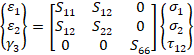 (2)
(2)
where the compliance coefficients of the lamina as follows (3):
 (3)
(3)
The S coefficients in (2) depend on Poisson’s and Young’s Modules of material. A symmetrical lamination is considered for the plies, so they have a specific thickness, specific material properties and a ply orientation, which for this case will be unidirectional through (1). The purpose is to find the deformation in direction and compare it with a finite element analysis to validate the results obtained in the simulation.
In this way, a numerical analysis in Matlab™ is implemented, which allows to relate the proposed equations by the macromechanical models with respect to the mechanical properties of the fabrics using conventional matrix operations. A deformation of ε1= 0.047 mm is then obtained for stress condition assumed, this result will be compared with simulation in next section.
2.4 Finite Element Method (FEM) validation
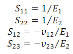
The purpose is to evaluate the analyzed condition in analytical model in order to validate the results, these are shown in Figure 6.
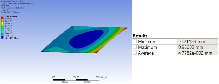
Finally, it is observed that the results obtained in the simulation correspond to those estimated in the analytical model, with respect to the average deformation of 0.047782 mm. With this value, there is an error of 1.7 %. This fact allows to propose more realistic load conditions for solar panel reinforcement and curved geometries, which will be discussed in next section.
3. RESULTS AND DISCUSSION: STRUCTURAL ANALYSIS
3.1. Analysis and simulation of reinforcement materials
Taking into account the validation of the simulation conditions for the flat panel, a more realistic scenario can then be proposed, including the curvature effects estimated above.
A load condition will then be assumed for direction 1, 2 and 3 of 1000 N. The approximate thickness for the analysis is 6 mm for each of the materials, in this way 16 layers are used for Kevlar and Fiberglass, while 20 layers are used for Carbon Fiber. For this purpose, an analysis in ANSYS®, specifically in composites ACP module is implemented, which allows establishing in detail different characteristics of the process, such as ply thickness and type of material. Effects on the deformation of Carbon Fiber, Glassfiber and Kevlar are analyzed and shown in Figure 7.
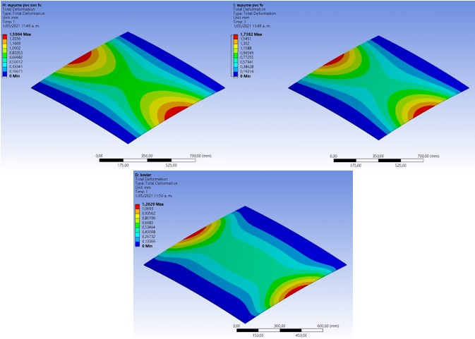
It is observed that the distribution of deformations is very similar for the materials analyzed, presenting the same patterns, according to the load conditions assumed, size finite element used was 10 mm. Likewise, Kevlar has less deformation with a value of 1.20 mm, followed by Carbon Fiber with 1.5 mm and finally, Glass fiber with 1.73 mm, precisely in Directional Deformation Z. In order to be more specific, the directional deformations are analyzed in the established coordinate system, which are shown in Table 3.
| Properties | Kevlar | Glass Fiber | Carbon Fiber |
| δx [mm] | 0.059 | 0.045 | 0.032 |
| δy [mm] | 0.021 | 0.025 | 0.022 |
| δz [mm] | 1.201 | 1.737 | 1.005 |
| m[kg] | 9.910 | 12.010 | 8.530 |
It can be seen that for plane state, the magnitude of the deformation does not change substantially, while the load in the direction 3 does have an important effect of the total deformation. In addition, it is necessary to analyze the stresses in each layer, as shown in Figure 8 and Figure 9.

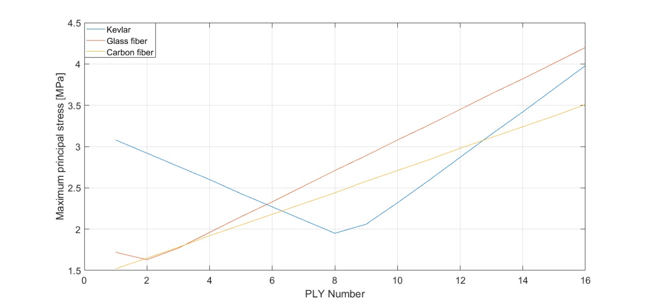
A very similar behavior is observed between Carbon Fiber and Glass fiber. The layers in contact with the cell receive a lower stress that increases according to the layer order. In contrast, Kevlar offers the lowest stresses in the intermediate layers of the reinforcement, while the outermost layers reach the maximum values. Likewise, shear stresses generated by the joint between the fabrics, which is an important factor in the failure of solar panels due to delamination which causes 10 % of the failures of solar panels [
Taking into account the minimum radius of curvature allowed in the cell, an analysis of the stresses and deformations obtained for different radius of curvature is performed, starting at a value of 6.5 m found previously, this behavior is shown in Figure 10 and Figure 11.
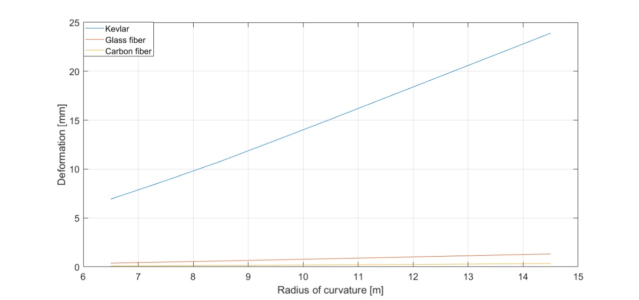
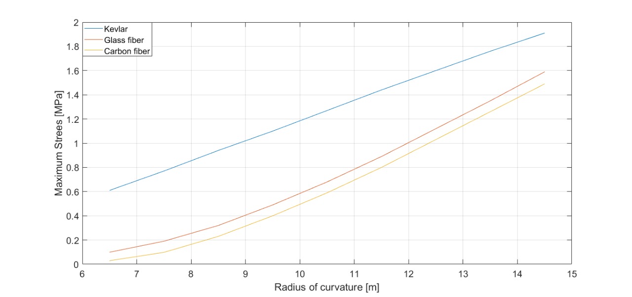
It should be noted that the panel tends to become flatter at higher values of radius of curvature. Thus, as the panel becomes flatter, the stress values also increase. Similarly, a deformation analysis is carried out for each of the materials, which is shown in Figure 10.
A big difference can be seen in the deformation behavior of the material, where Kevlar achieves the highest values, while Glassfiber and Carbon Fiber behave in a very similar way.
3.2. Analysis and simulation of encapsulation materials
Unlike the analysis presented for the reinforcement from orthotropic materials, the structural study performed for the encapsulation can be done with shell elements, due to their isotropic nature. Thus, a series of simulations were performed varying the thickness of the encapsulation, assuming that the solar cell is symmetrically immersed in the material for a radius of curvature of 6.51 m with thicknesses from 1 mm to 3 mm. Table 4 shows the results obtained for the total deformation and von Mises stress for the previously selected encapsulation materials.
Von Mises stress decreases as the thickness of the encapsulated material increases. The 2 mm thickness is desirable, as it is only 4 MPa different from the 3 mm thickness. The stress and deformation distribution for the 2 mm thickness is shown in Figure 12.
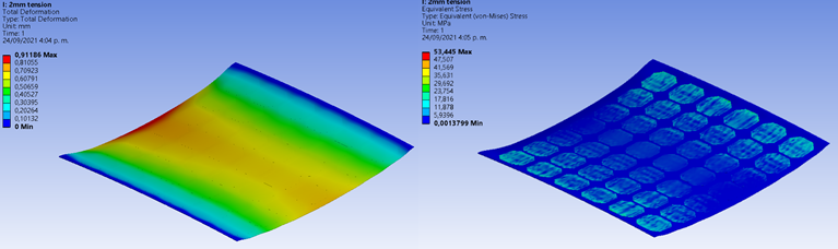
Considering supports at both ends of the panel and a load of uniformly distributed in the center, a distribution of deformations is obtained in which the maximum value of 0.91 mm is found at the point of load application. However, for the case of the stresses, it is found that the maximum magnitude of 53.44 MPa is close to the panel supports, while at the close point of load application, the stresses decrease considerably. This fact may affect the reliability of the solar panel discussed above. Therefore, for solar panel applications with curvature, it is recommended to use monocrystalline cells, since they present a fracture stress lower than 80 MPa, maintaining the assumed failure probability lower 5 % for perpendicular loads [
3.3. Convergence
The accuracy and confidence of the reinforcement results is based on the convergence graph, for nodes number in comparison with Total Deformation, this is shown in Figure 13.
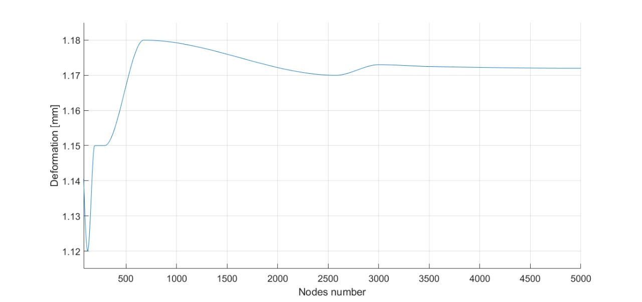
It is observed that from 3000 nodes, the values for deformation are stabilized in 1.17 mm, which allows to establish the characteristics of the mesh in the FEM study to obtain adequate values with the lowest computational cost.
4. CONCLUSIONS
An approach for the design of curved photovoltaic surfaces is presented, which allows addressing the structural requirements, according to the operating conditions, ensuring adequate reliability for the manufacturing of curved photovoltaic modules. An alternative way of manufacturing photovoltaics modules is proposed, which allows to obtain curved surfaces more easily than by conventional methods. The ability of the silicon solar cell to adapt to circular shapes was analyzed, estimating the radius of curvature that can be achieved and, additionally, a full structural analysis of the solar panel and the selection of materials from experimental tests is presented.
The structural performance of carbon fiber and glass fiber is very similar, starting from very low stresses in the first layers corresponding to 1.52 MPa and 1.72 MPa, respectively.
The growth of the Maximum Principal Stress for these materials is linear, taking a maximum magnitude of 4.04 MPa for Carbon Fiber and 4.02 MPa for Glassfiber in the layer furthest from the cell. This behavior is different for Kevlar, which has high stress in the first layer corresponding to 3,08 MPa, descending to the lowest value of 2,06 MPa in 9th layer, and then reaching its maximum value in the last layer corresponding to 4,98 MPa, which is a similar stress to Carbon Fiber and Fiberglass. This fact makes Glassfiber and Carbon Fiber desirable to be used as first reinforcement layers, since being in direct contact with the cell, it may causeless stresses decreasing the probability of cell failure. Similarly, Kevlar is the material with the best deformation behavior in Z direction, with a maximum value of 1.2 mm, followed by 1.5 mm for Carbon Fiber and 1.7 mm for Glassfiber in first layers. The estimation of these values strongly depends on the loads in direction 3, associated with impact loads of the system, so their presence directly influences the final selection of the material. Regarding weight. Carbon Fiber is the best performer with a total of 8.53 kg, however, more layers are needed to complete the same thickness as in the previous ones, so costs may increase considerably. In relation to Shear Stresses, the values in first layer for Carbon Fiber, Glassfiber and Kevlar are respectively 0.069,0.053 and 0.041 MPa.
The subsequent intermediate layers have the minimum shear stress values per layer.
Then, these values increase linearly until the last layer for Carbon Fiber (0.1 MPa) and Glassfiber (0.087 MPa). Kevlar presents a parabolic behavior, taking its minimum value corresponding to 0.019 MPa in the last layer. Considering the variation of the radius of curvature, Stresses and Strains increase as the geometry tends to become flatter. This fact is based on the variation of the moment of inertia, which is lower when there is large radius of curvature (flat geometry), so there is less performance under stress and deformation conditions. Maximum Stresses and Deformations for Carbon Fiber are 1.49 MPa and 0.34 mm, while for glass fiber the values obtained are 1.59 MPa and 1.32 mm, respectively. Kevlar is the material that performs worst, since it presents maximum stress of 1.91 MPa and important deformations ranging from 6.93 mm to 23.9 mm; these big displacements can be transmitted to the cell, which substantially reduces its reliability. With respect to the encapsulation materials, the structural influence of the encapsulation material on the solar cell needs to be studied in more detail, as the reliability of the complete system can be significantly compromised. Due to the stresses obtained in the simulations with the encapsulated material, it is advisable to use monocrystalline cells for photovoltaic surface applications with curvature, since they have better structural resistance than polycrystalline cells.
5. FUTURE WORK
Considering the multiphysics nature of photovoltaic module operation, it is necessary to address the thermal, optical, and electrical aspects of the design and fabrication of photovoltaic surfaces using composite materials. From the thermal point of view, it will be important to analyze the thermal properties of the encapsulation-reinforcement arrangement and its implication in the dissipation of the generated heat, which is the most important energy loss of the system. Likewise, the exploration of encapsulation materials with better optical behavior could improve photon transmittance. The use of polarized filters could reflect the infrared light spectrum, which is responsible for temperature increases and therefore energy losses that could be harnessed. These combined physical effects have important implications on the overall performance of the photovoltaic module, so that the plotting of VI and PV curves for panels made of composite materials as a function of the physical phenomena described may be a promising horizon in the field of photovoltaic solar energy.
6. ACKNOWLEDGMENTS
Authors would like to thank Universidad EAFIT to support this research through the Research Assistantship grant from project 953-000012. This research has been also developed in the framework of the “ENERGETICA 2030” Research Program, with code 58667 in the “Colombia Científica” initiative, funded by The World Bank through the call “778-2017 Scientific Ecosystems”, managed by the Colombian Ministry of Science, Technology and Innovation (Minciencias), with contract No. FP44842-210-2018.
CONFLICTS OF INTEREST
All authors declare that there are no financial, professional or personal interests that could inappropriately influence the results obtained or the interpretations proposed.
AUTHOR CONTRIBUTIONS
Gabriel Espitia-Mesa: published this paper as part of his doctoral studies, his contribution proposes the design approach for photovoltaic surfaces with curvature through the analysis of operational requirements, material selection and computational validation.
Efraín Hernández-Pedraza, and Santiago Molina-Tamayo: contributed to the development of the analytical models presented and their computational validation and experimental analysis.
Ricardo Mejía-Gutiérrez is the director of Gabriel Espitia-Mesa's doctoral program and proposed the main idea of the article corresponding to the use of composite materials in the manufacture of composite materials due to his great experience in the alternative energy sector, and also contributed to the writing of the final manuscript.
7. REFERENCES
- arrow_upward [1] G. Espitia-Mesa; E. Hernández-Pedraza; S. Molina-Tamayo; R. Mejía-Gutiérrez,” Modeling, analysis and simulation of curved solar cell’s encapsulation reinforcement”, in Workshop on Engineering Applications, Bogotá: Springer, pp. 468–479, 2021.
- arrow_upward [2] A. F. Zobaa; R. C. Bansal, Handbook of Renewable Energy Technology. World Scientific, 2011. https://doi.org/10.1142/7489
- arrow_upward [3] J. Hauff et al., Unlocking the sunbelt potential of photovoltaics. European Photovoltaic Industry Association and Others, 2010.
- arrow_upward [4] Y. B. Assoa; D. Levrard, “A lightweight triangular building integrated photovoltaic module”. Applied Energy, vol. 279, p. 115816, Dec. 2020. https://doi.org/10.1016/j.apenergy.2020.115816
- arrow_upward [5] P. Jayathissa; S. Caranovic; J. Hofer; Z. Nagy; A. Schlueter, “Performative design environment for kinetic photovoltaic architecture”, Automation in Construction, vol. 93, pp. 339–347, Sep. 2018. https://doi.org/10.1016/j.autcon.2018.05.013
- arrow_upward [6] E. Saretta; P. Caputo; F. Frontini, “An integrated 3D GIS-based method for estimating the urban potential of BIPV retrofit of façades”, Sustainable Cities and Society, vol. 62, p. 102410, Nov. 2020. https://doi.org/10.1016/j.scs.2020.102410
- arrow_upward [7] W. Liu; T. T. Chow, “Experimental and numerical analysis of solar absorbing metallic facade panel with embedded heat-pipe-array”, Applied Energy, vol. 265, p. 114736, May. 2020. https://doi.org/10.1016/j.apenergy.2020.114736
- arrow_upward [8] S. R. Maadi; M. Khatibi; E. Ebrahimnia-Bajestan; D. Wood, “Coupled thermal-optical numerical modeling of PV/T module – combining CFD approach and two-band radiation DO model”, Energy Conversion and Management, vol. 198, p. 111781, Oct. 2019. https://doi.org/10.1016/j.enconman.2019.111781
- arrow_upward [9] M. C. Brito; T. Santos; F. Moura; D. Pera; J. Rocha, “Urban solar potential for vehicle integrated photovoltaics”, Transportation Research Part D: Transport and Environment, vol. 94, p. 102810, May. 2021. https://doi.org/10.1016/j.trd.2021.102810
- arrow_upward [10] H. Martin; R. Buffat; D. Bucher; J. Hamper; M. Raubal, “Using rooftop photovoltaic generation to cover individual electric vehicle demand—a detailed case study”. Renewable and Sustainable Energy Reviews, vol. 157, p. 111969, Jan. 2022.
- arrow_upward [11] Y. Ota; K. Araki; A. Nagaoka; K. Nishioka; Facilitating vehicle-integrated photovoltaics by considering the radius of curvature of the roof surface for solar cell coverage. Cleaner Engineering and Technology, vol. 7, p. 100446, Apr. 2022. https://doi.org/10.1016/j.clet.2022.100446
- arrow_upward [12] D. J. Vergados; I. Mamounakis; P. Makris; E. Varvarigos, “Prosumer clustering into virtual microgrids for cost reduction in renewable energy trading markets”. Sustainable Energy, Grids and Networks, vol. 7, pp. 90–103, Sep. 2016. https://doi.org/10.1016/j.segan.2016.06.002
- arrow_upward [13] V. Makarskas; M. Jurevičius; J. Zakis; A. Kilikevičius; S. Borodinas; J. Matijošius; K. Kilikevičienė, “Investigation of the influence of hail mechanical impact parameters on photovoltaic modules”, Engineering Failure Analysis, vol. 124, p. 105309, Jun. 2021. https://doi.org/10.1016/j.engfailanal.2021.105309
- arrow_upward [14] H. Hanifi; C. Pfau; M. Turek; J. Schneider, “A practical optical and electrical model to estimate the power losses and quantification of different heat sources in silicon based PV modules”. Renewable Energy, vol. 127, pp. 602–612, Nov. 2018. https://doi.org/10.1016/j.renene.2018.04.060
- arrow_upward [15] G. Wang; Y. Yao; B. Wang; P. Hu, “Design and thermodynamic analysis of aninnovative hybrid solar PV-CT system with multi-segment PV panels”. SustainableEnergy Technologies and Assessments, vol. 37, p. 100631, Feb. 2020. https://doi.org/10.1016/j.seta.2020.100631
- arrow_upward [16] A. E. Kabeel; M. Abdelgaied, “Performance enhancement of a photovoltaic panel with reflectors and cooling coupled to a solar still with air injection”, Journal of Cleaner Production, vol. 224, pp. 40–49, Jul. 2019. https://doi.org/10.1016/j.jclepro.2019.03.199
- arrow_upward [17] S. Kiyaee; Y. Saboohi; A. Z. Moshfegh, “A new designed linear Fresnel lens solar concentrator based on spectral splitting for passive cooling of solar cells”, Energy Conversion and Management, vol. 230, p. 113782, Feb. 2021. https://doi.org/10.1016/j.enconman.2020.113782
- arrow_upward [18] S. Kim; S. Kasashima; P. Sichanugrist; T. Kobayashi; T. Nakada; M. Konagai, “Development of thin-film solar cells using solar spectrum splitting technique”, Solar energy materials and solar cells, vol. 119, pp. 214–218, Dec. 2013. https://doi.org/10.1016/j.solmat.2013.07.011
- arrow_upward [19] A. Mojiri; R. Taylor; E. Thomsen; G. Rosengarten, “Spectral beam splitting for efficient conversion of solar energy—a review”, Renewable and Sustainable Energy Reviews, vol. 28, pp. 654–663, Dec. 2013. https://doi.org/10.1016/j.rser.2013.08.026
- arrow_upward [20] F. Kaule; W. Wang; S. Schoenfelder, “Modeling and testing the mechanical strength of solar cells”, Solar energy materials and solar cells, vol. 120, Part. A, pp. 441–447, Jan. 2014. https://doi.org/10.1016/j.solmat.2013.06.048
- arrow_upward [21] M. Sander; S. Dietrich; M. Pander; M. Ebert; J. Bagdahn, “Systematic investigation of cracks in encapsulated solar cells after mechanical loading”, Solar Energy Materials and Solar Cells, vol. 111, pp. 82–89, Apr. 2013. https://doi.org/10.1016/j.solmat.2012.12.031
- arrow_upward[22] S. Dietrich; M. Pander; M. Sander; S. H. Schulze; M. Ebert, “Mechanical and thermomechanical assessment of encapsulated solar cells by finite-element-simulation”, in: Reliability of photovoltaic cells, modules, components, and systems III, vol. 7773, p. 77730, 2010. https://doi.org/10.1117/12.860661
- arrow_upward [23] S. Roy; M. S. Baruah; S. Sahu; B. B. Nayak, “Computational analysis on the thermal and mechanical properties of thin film solar cells”, Materials Today: Proceedings, vol. 44, Part. 1, pp. 1207-1213, 2021. https://doi.org/10.1016/j.matpr.2020.11.241
- arrow_upward [24] G. F. Abdelal; A. Atef, “Thermal fatigue analysis of solar panel structure for micro-satellite applications”, International Journal of Mechanics and Materials in Design, vol. 4, no. 1, pp. 53–62, Jan. 2008. https://doi.org/10.1007/s10999-008-9057-3
- arrow_upward [25] N. F. M. Roozenburg; N. G. Cross, “Models of the design process: integrating across the disciplines”, Design studies, vol. 12, no. 4, pp. 215–220, Oct. 1991. https://doi.org/10.1016/0142-694X(91)90034-T
- arrow_upward [26] D. G. Ullman, The mechanical design process. New York. McGraw-Hill. 1992.
- arrow_upward [27] J. Estrada; J. A. Camacho; M. T. Restrepo; C. M. Parra, “Parámetros antropométricos de la población laboral colombiana 1995”, Revista Facultad Nacional de Salud Pública, vol. 15, no. 2, pp. 112-139, Nov. 1998.
- arrow_upward [28] M. M. Ansari; A. Chakrabarti, Effect of bullet shape and h/a ratio on ballistic impact behaviour of FRP composite plate: A numerical study. International Journal of Research in Engineering and Technology, vol. 4, no. 13, pp. 435-442, Dec. 2015.
- arrow_upward [29] S. Bernal del Río, “Influencing the performance of a Building Integrated Low-Concentration Photovoltaic (BICPV) system by adapting an Anti-Reflective Coating (ARC) with a pyramidal texture”, (Ph.D. thesis), Engineering School, Universidad EAFIT, Medellín, 2021. http://hdl.handle.net/10784/29629
- arrow_upward [30] S. N. K. Sagar; M. Sreekumar, “Miniaturized flexible flow pump using SMA actuator”, Procedia Engineering, vol. 64, pp. 896–906, 2013. https://doi.org/10.1016/j.proeng.2013.09.166
- arrow_upward [31] E. J. Barbero, Introduction to composite materials design. CRC Press, 2017.
- arrow_upward [32] M. S. Chowdhury et al., "An overview of solar photovoltaic panels’ end-of-life material recycling". Energy Strategy Reviews, vol. 27, p. 100431, Jan. 2020. https://doi.org/10.1016/j.esr.2019.100431